System-Level Requirements
Functional requirements
At a high level, the system must be able to identify where in the environment litter exists. Once that is done, it must be able to follow a path to the litter and collect it off the ground. Next, it must return to its base so that the litter can be disposed of. The operating environment may be grass or sand, for testing purposes. These have been compiled into a list of functional requirements below:
The system shall
M.R.1 Locate litter in the operating environment.
M.R.2 Plan a path to both locate and collect litter.
M.R.3 Collect and store litter from the surface of the ground.
M.R.4 Return to base upon completion of the mission.
M.R.5 Operate on sand and grass environments.
D.R.1 Identify and avoid obstacles
D.R.2 Monitor the status of the system in real-time
Non-functional requirements
The functional and performance requirements highlight the high-level tasks of a machine and how well those tasks are achieved based on measurement criteria. But there are few other requirements – the Non-functional Requirements – that the system has to fulfill for it to work harmoniously on a whole.
The system shall
M.N.1 Be easily maintainable
M.N.2 Be within budget excluding given resources
M.N.3 Have an easily accessible emergency stop
M.N.4 Adhere to Federal Aviation Administration (FAA) regulations
D.N.1 Monitor the litter capacity in real time
D.N.2 Alert people in the vicinity of the system by making sound
Note M.N – Mandatory non-functional requirement. D.N – Desired non-functional requirements.
Performance requirements
The system will
M.P.1.1 Scout an area of 128 sq. meters.
This is the size of a standard sand volleyball court, which is our planned testing site.
M.P.1.2 Identify 50% of litter in the scout area.
The system must be able to identify litter to perform its primary task. A 70% detection rate and a 70% identification rate are reasonable to expect from current algorithms, which compounds to 50% identification.
M.P.1.3 Identify litter with a profile of at least 65 sq. cm, at most 13 cm tall.
This is the profile of a coffee cup or solo cup, which are some of the most common litter found on a beach.
M.P.1.4 Correctly locate to within 0.7m of ground truth.
The system’s pickup mechanism requires that it drive over the litter, so it’s very important that the system knows the litter’s location within the width of the UGV.
M.P.2 Plan a successful path 80% of the time.
A high level of navigation accuracy is required, and this is a suitable goal for testing.
M.P.3.1 Collect 70% of the identified empty coffee cups and solo cups.
The ability to collect identified litter is vital to the system’s primary functionality.
M.P.3.2 Hold at least 0.05 cubic meters of litter.
The system must be able to hold litter to perform its primary responsibility, this capacity matches the size of the pickup trailer to the size of a Husky UGV.
M.P.4 Successfully complete the collection task within 20 minutes.
Bringing the litter off the beach to a known location is an important part of the user experience.
M.P.5 Operate on flat terrain.
The system must be able to operate in its primary operating environment, which for most beaches is flat.
D.P.1 Identify obstacles of profile greater than 1m2
Avoiding obstacles would increase the resilience of the system to uncertain situations.
D.P.2 Navigate around obstacles within 5 min
Navigating around an obstacle in a reasonable amount of time will make the system more useful in uncertain situations.
D.P.3 Monitor the sensor status, battery status at the real-time and log the data
Additional sensor data are necessary to add more advanced functionality.
Functional Architecture
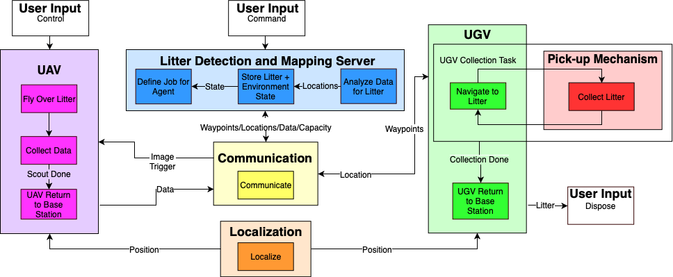
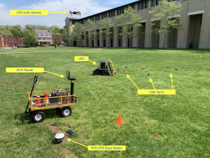
Our system consists of three major physical entities: The UAV, the UGV and a central server. Outside of these physical entities, our system also has a communication subsystem, which is spread across all agents. Additionally, our localization subsystem will also be operating across all agents. The server contains the mapping and vision subsystems, the outputs of which are broadcasted to the UAV and UGV accordingly.
The UAV is responsible for covering the operating environment and scouting for litter. The central server defines waypoints for the UAV to cover the area and communicates them to the UAV. The UAV’s onboard controller takes those waypoints and follows the intended trajectory. Along its scout path, it periodically collects data about the environment (images, locations, etc.). Once this scout task is done, the UAV returns to its base and then transmits the data it collected back to the central server.
The server is responsible for defining and managing the tasks being done by the agents. One of its primary purposes is to compute waypoints for the UAV and UGV for their respective jobs (scouting and collection). In addition, the server takes the data collected by the UAV and analyzes it for litter in the environment. Using that information, plus the other metadata collected by the UAV, the server builds a map of the litter in the environment. This map is used to define the collection task performed by the UGV.
The UGV’s role is to traverse the operating environment and collect litter that was identified by the UAV. The UGV receives waypoints from the server and follows the intended trajectory. It also has a litter pick-up mechanism attached to it which is capable of retrieving litter (solo cups and coffee cups) off the ground and storing it for the duration of its collection task.
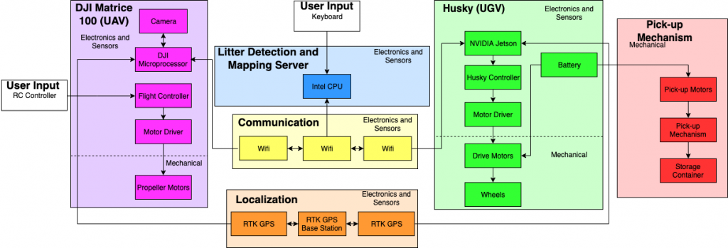
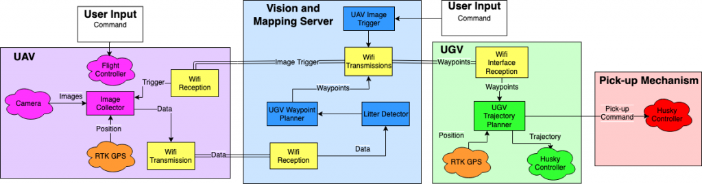
Cyberphysical Architecture
As mentioned in the Functional Architecture, our system can be split up into three different agents: the UAV, UGV, and server. We have expanded on our functional architecture to a cyber-physical architecture. This cyber-physical architecture is motivated by the subsystem (and in some cases component) trade studies.
All our major entities will be using 2.4GHz radio to communicate with each other. Our localization subsystem will be implemented using RTK GPS.
The UAV, which will be a DJI Matrice 100 drone, will have its own onboard microcontroller and flight controller. These will be used to fly the vehicle and collect data from the camera and localization subsystem. The major software components of the UAV will involve a trajectory planner and an image collector to interface with the camera.
The UGV, which will be a Husky, will also have its own onboard controller. In addition to that, we will have a microcontroller (Arduino Uno) to control the pickup mechanism and a microprocessor (NVIDIA Jetson) to handle the other high-level decision-making responsibilities while the UGV is on its collection task.
The server itself will have both a CPU and GPU to support computationally intensive computer vision algorithms for litter detection and localization.
Below, we have included our cyber-physical architecture. We have split it up into two diagrams to make it easier to track. The one on the top is our software architecture while the one on the bottom is our hardware/electrical architecture. Both the diagrams below, as well as the functional architecture diagram, are color-coded so that the functions can be mapped to the subsystems/components that will be performing specific tasks.
Overall System
Subsystem Descriptions
Litter Detection
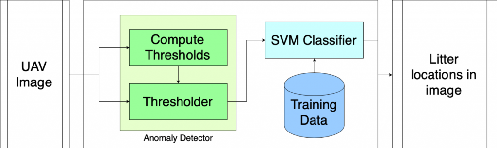
Our computer vision pipeline is designed to detect specific litter objects on the ground from images taken by the UAV. The diagram below depicts our litter detection subsystem. The input is a 1280 x 720 image taken by the UAV and the outputs are the litter locations in the image (pixels). First, the image is passed through an anomaly detector. Since our environments have homogeneous backgrounds (green grass or brown sand) that dominate the image, we determine the distribution of colors in the image. Those distributions are used to threshold the image and identify objects that don’t match the appearance of the background (anomalies). This is done by computing the mean and standard deviation of all pixel values in the image and thresholding based on how many standard deviations away from the mean any given pixel is. These anomalous patches of the image are then passed to a Support Vector Machine (SVM) classifier, which determines whether the object or objects in those patches are actual litter items or not. We then combine nearby patches (using a technique like non-maximum suppression) to combine overlapping patches and return a set of pixels locations in the image that correspond to litter objects.
Pick-up Mechanism
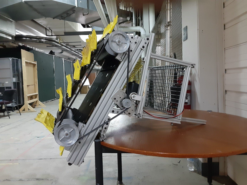
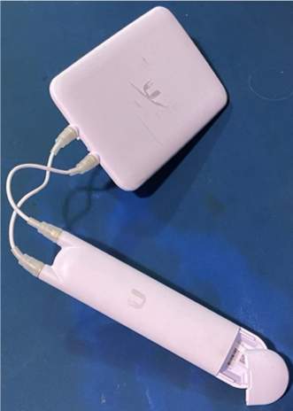
The pick-up mechanism, shown in Figure 7, would collect and store litter from the environment. The subsystem is attached to the front of the Husky. The mechanism collected litter using a rotating conveyor, driven by a single low-speed high torque DC motor. The conveyor belt was built using an off the shelf agricultural pick-up belt and pick-up teeth. The teeth grab litter lying on the ground and compress it into the conveyor and carry it up to the storage compartment, also on the Husky. The pick-up teeth were modified to have a mesh between the teeth to more effectively pick-up litter.
RTK-GPS
The RTK subsystem we use for agent’s localization is an RTK-GPS system. Real-time kinematic (RTK) positioning is a satellite navigation technique used to enhance the precision of position data derived from satellite-based positioning systems (global navigation satellite systems, GNSS) such as GPS, GLONASS. It uses measurements of the phase of the signal’s carrier wave in addition to the information content of the signal and relies on a single reference station or interpolated virtual station to provide real-time corrections, providing up to centimeter-level accuracy[v]
There were Emlid RTK GPS modules mounted on both the UAV and UGV subsystems to provide localization information. The modules used a “fix and hold” correction from the base station, which is more stable than a continuously updating correction. However, if the UAV and UGV were activated at different times they would receive different corrections from the base station, creating a permanent offset between the agents. To avoid this, we simultaneously re-initialize the RTK GPS modules at the beginning of each field test to ensure both have the same correction.
Communication
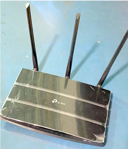
In order to achieve multi-agent communication, we set up a local Wi-Fi network, to which all agents in our system connect. Our communication subsystem consists of a Wi-Fi router and a Wi-Fi extender. Each agent (UAV, UGV, Server) has its own static IP so that it is easier to set up the communication pipeline between them. Along with the RTK GPS system, each Rover receiver connects to the base station through the Wi-Fi Network.
During the UAV scout operation, the unidirectional Wi-Fi extender allows the server to interact seamlessly with the UAV onboard computer. The ROS service calls are triggered on the UAV, during its flight, from the server on the ground.
The ground systems are interfaced with the server via a local Wi-Fi network. Figure 10 shows our Wi-Fi router and Figure 11 shows the Wi-Fi extender.
Localization
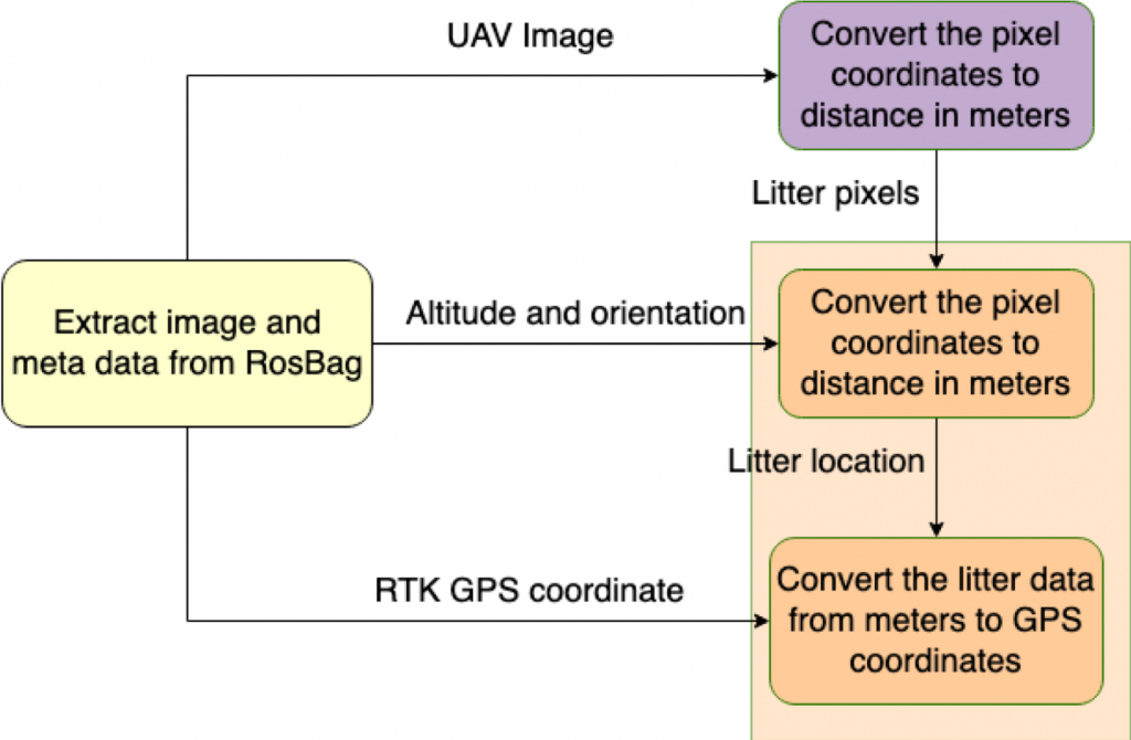
The flight data – images, metadata (RTK GPS of the UAV, attitude, and altitude) is stored on the UAV onboard computer in a time-stamped folder via trigger of a ROS service call on the UAV onboard computer from the server. After the UAV scout operation, the rosbags are transferred to the server via wireless secure copy (scp).
The first diagram below shows the localization pipeline. The rosbags from the UAV are processed to extract images and metadata. The images are passed to the computer vision subsystem and corresponding litter pixel coordinates are obtained. Those pixel coordinates are then used to compute the world coordinates of the litter items using the formula in the second diagram below.
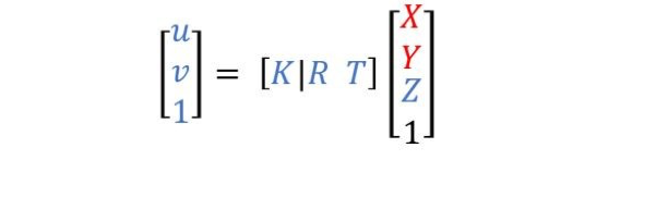
- K – camera intrinsics, which are obtained by calibrating the UAV onboard camera
- R – Rotation matrix of the camera on the UAV
- T – The x, y, z translation of the camera from the UAV center
- u, v – Litter pixels in an image
- X, Y, Z – Litter position in world coordinates (m)
Motion Planning and Control
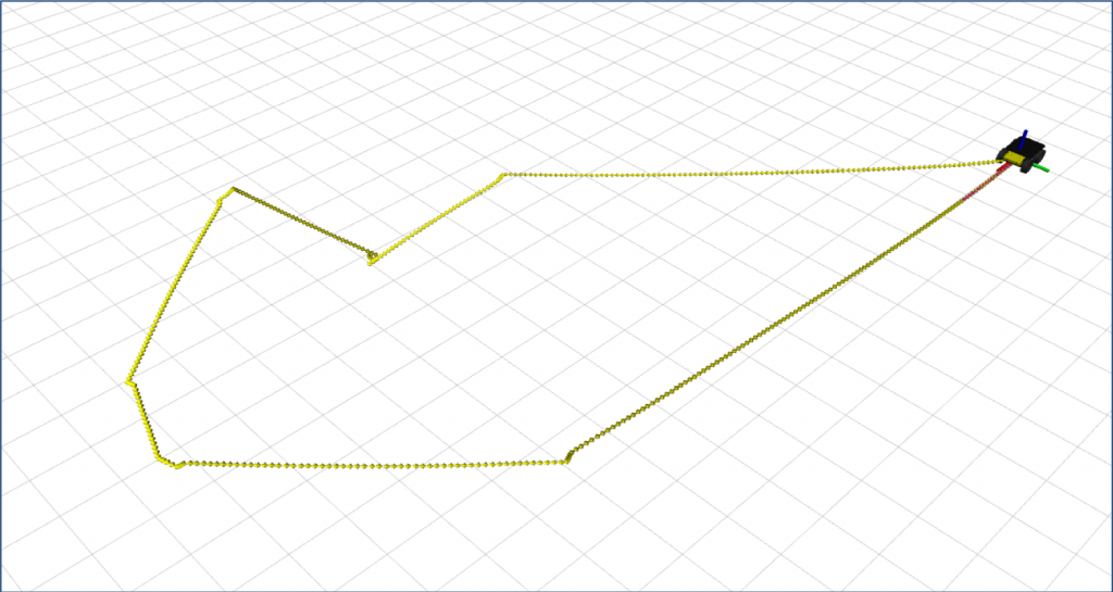
Before the server publishes the cluster centers to the UGV, it determines the order in which the UGV should collect the litter using a greedy algorithm as shown in the first figure below. The greedy algorithm first sends the UGV to the litter which is closest to its current location, followed by the litter closest to the second litter and repeats this until all litter has been sorted. The server then publishes the ordered cluster centers to the UGV along with the cluster variance.
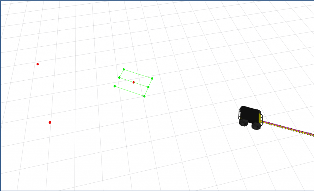
The UGV will create a coverage pattern around each of the cluster centers when it is time for the UGV to approach it. The coverage pattern is Zamboni like, to minimize the number of immediate turns the UGV does. The UGV will dynamically choose how many lanes the Zamboni needs to pick-up successfully collect the litter. The second figure below shows a coverage pattern with 3 lanes, which means the variance was relatively low and we are relatively confident in the litter’s location. The red dots represent cluster centers.
UAV
A DJI Matrice 100 will act as the UAV for our system. This platform includes a camera. The UAV subsystem will scout the area of operation for litter collecting images and location data and passing the data on to the central server for processing.
UGV
A Clearpath Husky will act as the UGV for our system. The UGV’s role in the system will be transporting the litter pickup mechanism to litter clusters. The UGV will also be the hub for communication with the Server.