Dynamics and Controls Subsystem Progress
The Dynamics and Control subsystem is where vehicle simulator development, vehicle dynamics and tire modeling, online model learning, and vehicle controls are designed and implemented. The initial vehicle model that has been implemented as a baseline is a dynamic bicycle model with parameters that map to our test vehicle platform. The next iteration would be to implement a neural network or model based reinforcement learning technique for representing the vehicle dynamics by taking in state feedback from simulation or on-board sensors and training the model to learn edge weights that allow accurate predictions of the vehicles future states.
January 6th, 2020
Initialized BitBucket repository that will be used for revision control and documentation of ongoing software development within this subsystem.
January 24th, 2020
After doing immense amounts of research on different environments that could be used for performing vehicle simulation, our team decided to move forward with developing our simulation within MATLAB/Simulink. This had to do with the fact that compared to CARLA or Gazebo, we had more freedom for design choices, and had strong documentation and resources available from MathWorks, whereas the other two mentioned environments would limit our ability to model the nonlinear dynamics of our vehicle.
February 7th, 2020
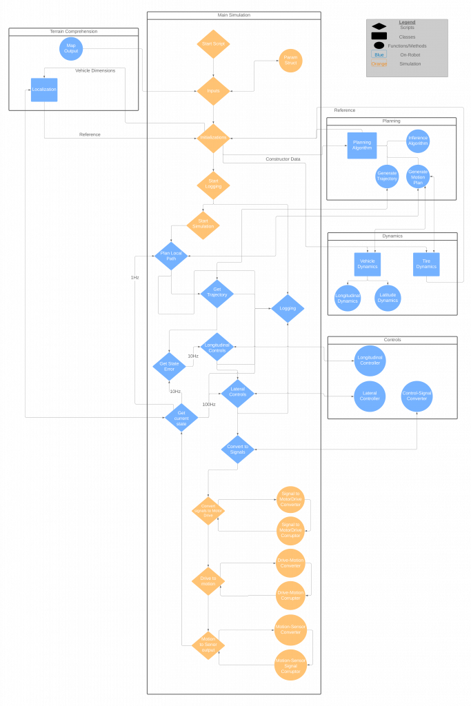
A pipeline diagram that lays out the overall structure and flow of data transfer throughout the simulator and subsequent robot was created, which we believe will be useful to refer to when constructing our software. This allows us to make more informed decisions about inputs and outputs from various functions, and helps determine what data and methods should be encased in class objects.
February 21st, 2020
First iteration of vehicle simulation was successfully implemented within MATLAB, with the first demonstration consisting of a simple PI longitudinal controller. A visualization of this can be seen below, where the blue rectangle represents the vehicle and the dotted red line represents the straight path:
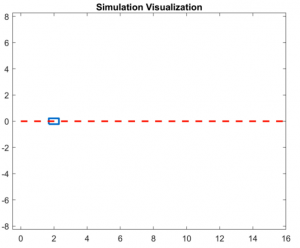
The visualization script uses homogeneous transformations to plot how the vehicle travels through space.
March 6th, 2020
We have been prototyping various control algorithms for the lateral control of our robotic system. We are looking at methods that we can start off by implementing simplified versions, and then add in more complex features over time. We will be starting off with linearized tire dynamics, and fixed parameter vehicle model, and moving forward we will be implementing a fiala brush tire model based on data gathered during testing, along with implementing a learning-based approach to update model parameters on the vehicle as the system traverses a trajectory.
March 24th, 2020
So far for lateral control we have been prototyping a Stanley controller, which has provided stable control, but has also produced a fairly large cross-track error, as can be seen in the image below:
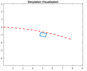
This method is currently being refined.
March 28th, 2020
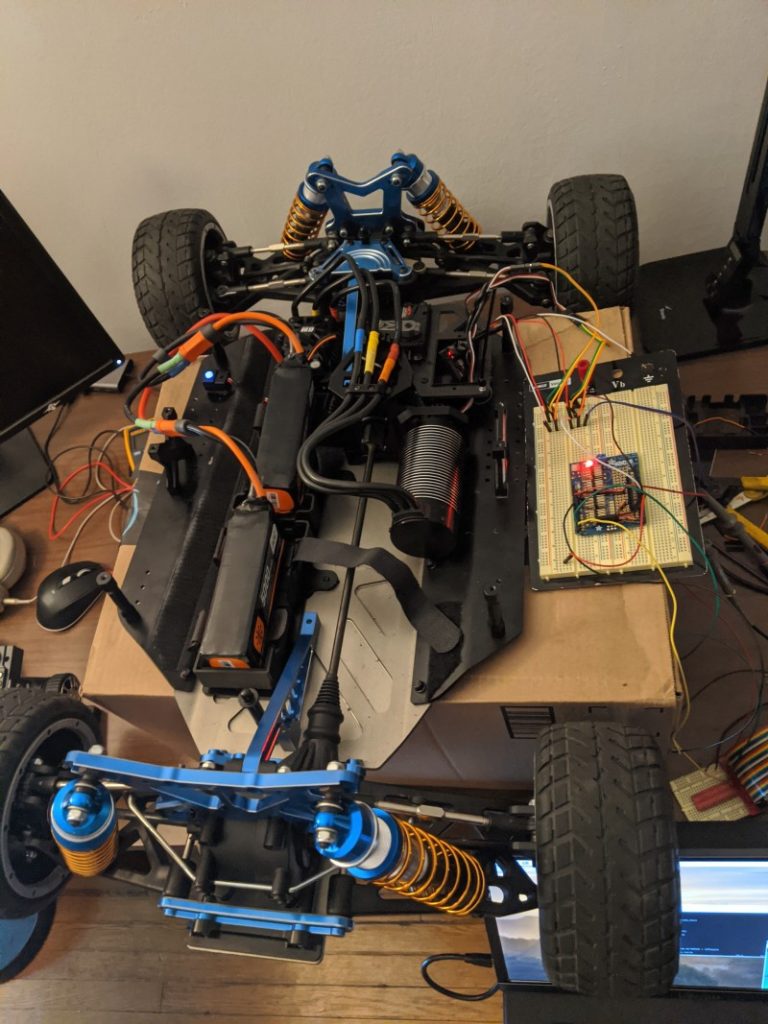
Today, we successfully produced a prototyping circuit for the low-level vehicle controls. We are currently using a PWM board from Adafruit, that we communicate with over I2C from our Jetson Xavier, to send control signals to our vehicle’s electronic speed controller (ESC). With this circuit, we have been able to adjust the steering angle and the drive motor speed. Going forward, this will be used as a way to prototype onboard vehicle controls, once they are transferred from simulation.
April 1st, 2020
Today, the a simplified version of the Stanley controller that has been worked on within simulation has been tuned and is now providing considerably better tracking performance. A test trajectory and the vehicle’s subsequent tracking performance can be seen below:
April 10th, 2020
We have been able to make significant progress on getting a full version of the Stanley lateral control algorithm implemented properly, and then in turn testing and tuning control gains on various trajectories. This implementation is specifically based on the steering control law for a dynamic bicycle model, which can be seen below:
![]()
The main upgrade in the controller comes from adding in the k_d,steer gain terms into the control law. These terms allow the commanded steering angle to be damped and help prevent chatter in the control effort, along with assisting with stability in the control law.
April 17th, 2020
Significant time was spent converting the control algorithms that were tested and tuned in simulation into code that could be used onboard our robot. The simulation code is all written in MATLAB, while our onboard software is built within Python. All of the necessary code to control the robot has been written and committed to our BitBucket repository, which includes ROS callback functions that take messages from the motion planning and localization pipelines and pass them to the control pipeline.
April 20th, 2020
Over the past few days, the focus has been on integrating the Dynamics and Controls and Motion Planning pipelines within our simulation, which has ultimately been successful. This allows us to simultaneously prototype control algorithms, tune gains, and test motion planning algorithms all within one environment, which has immense utility for our project, since we can see how robust each subsystem is when changes are made to others, which will cut out a lot of time wasted during integration on the physical robot. This has allowed for more complex maps to be used for generating the simulation videos as well, with the videos representing our spring validation demonstrations #2 and #3 being shown below, respectively:
April 25th, 2020
Significant progress has been on the onboard software pipeline that is deployed on the physical robot. To show that the vehicle is capable of being controlled solely by the onboard computer, an open loop control test was performed. Here is the video:
April 27th, 2020
This video displays the final capabilities of the integrated dynamics, controls, planning, and localization pipelines within simulation for the spring semester. A complicated map with many varying radius turns are present, and the vehicle is able to track with great performance.
August 26th, 2020
The team has discussed what the system development priorities are for the upcoming semester, and have decided to focus on minor refinements to improve the controller code tunability and efficiency, but not on major overhauls. In the event that the rest of the system is brought to a coherent and functional state, more advanced controls techniques may be implemented.
September 23rd, 2020
During a code review of the control code repository, it was found that the conversion of the throttle and steering command calculations to PWM signal values was resulting in a positive feedback loop that would cause the controller to consistently go unstable. These bugs were fixed and committed.
October 9th, 2020
Feature added to the Interface and the vehicle controller, where steering and throttle commands are able to be sent over ROS to control the vehicle. This was implemented due to a hardware issue with the RC receiver, which prevented our team from being able to manual control the robot, whether
October 15th, 2020
The team began focusing on testing the controller on hardware by starting with longitudinal control testing. This consisted of pre-generated trajectories that have the vehicle speed up, slow down, and arrive at various waypoints at various distances.
November 4th
Recently, the team has been doing a significant amount of field testing in which the longitudinal and lateral controller gains have been being tuned. While we have seen improvement in path tracking capabilities, we have also noticed that the vehicle appears to track with dissimilar performance when tracking a left vs. right turn
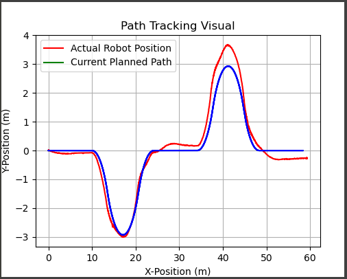
November 10th
Full vehicle tracking pipeline functioning well together. A video and a few examples plots of tracked trajectory performance can be seen below: