Platform and Hardware Subsystem Progress
The Platform and Hardware subsystem will encompass all tasks relating to the reverse-engineering of our 1/5 scale RC camera car, sensing and computing device selection and integration, power distribution circuit design and manufacturing, and the design of a waterproof enclosure for on-board electronics. Our vehicle’s weight after integrating the ADAPT system will be ~60 lbs. We have completed our CAD models for all of our designed components, and have shifted into the manufacturing phase, along with the calibration of our specified sensors. See more details about our process below!
Spring 2020 Development
January 10th, 2020
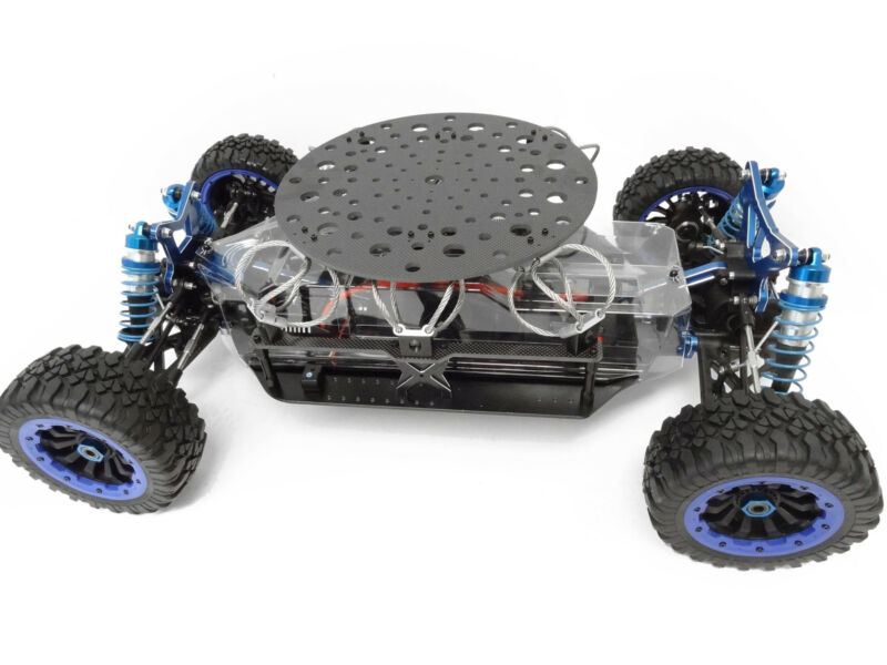
On this day, we received our vehicle platform, which is a 1/5th Scale RC Camera Car that we will retrofit to convert into our robotic system. An image of the unmodified vehicle can be seen below:
February 28th, 2020
Our CAD models have been finalized for all the components needed to move to manufacturing our enclosure and vehicle mounting system.
March 9th, 2020
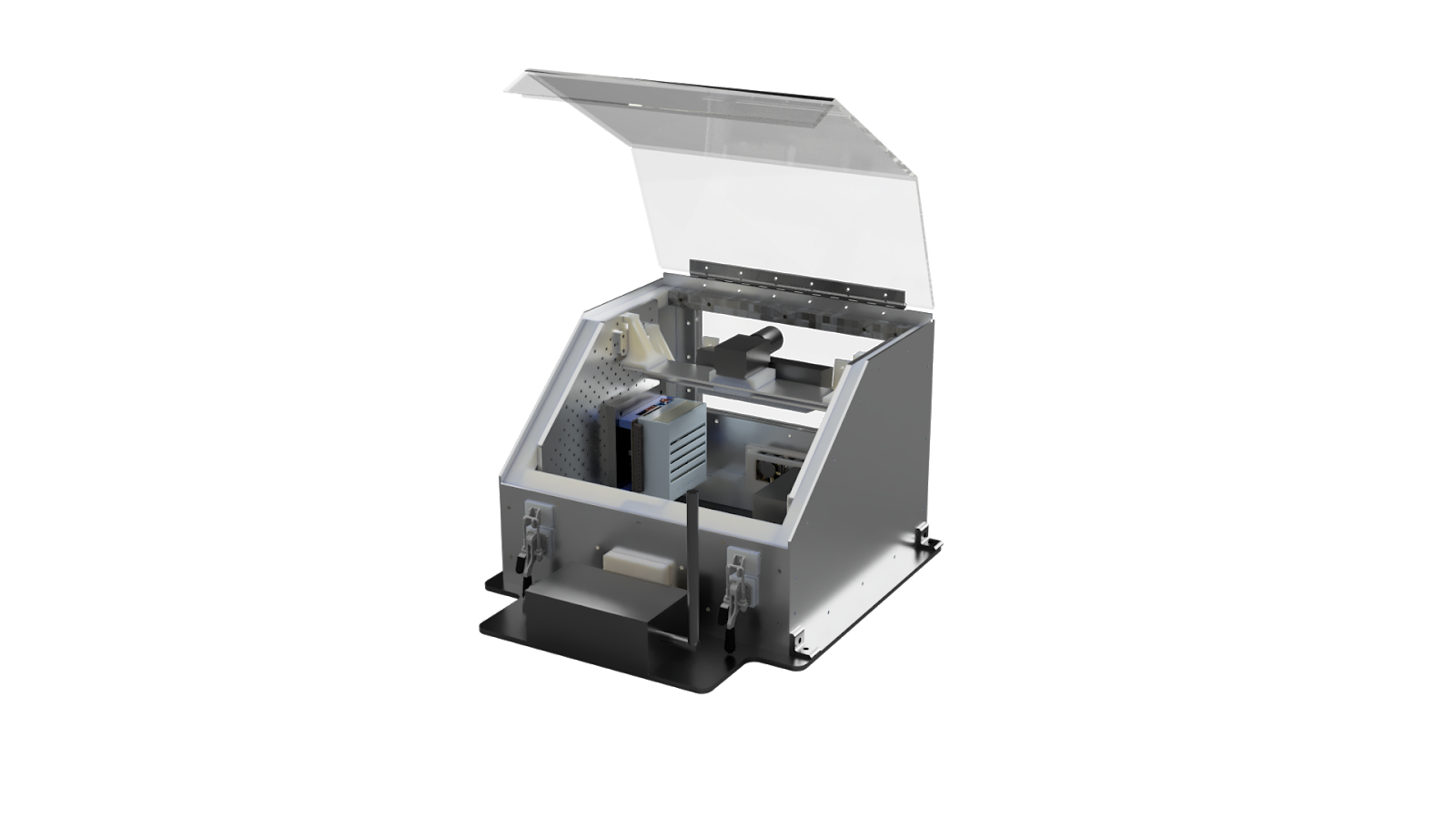
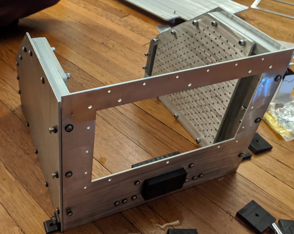
We received our external enclosure plates after having them cut on a water jet. Our team worked closely with the manufacturing facilities at the National Robotics Engineering Center (NREC) to have them cut. A simple mock-up of the enclosure as it would sit on the vehicle can be seen below:
As shown above, the enclosure window is large enough for our perception sensors to be adjusted to various heights to study how the height and angle of these sensors can affect the performance of our adverse terrain detection system.
March 25th, 2020
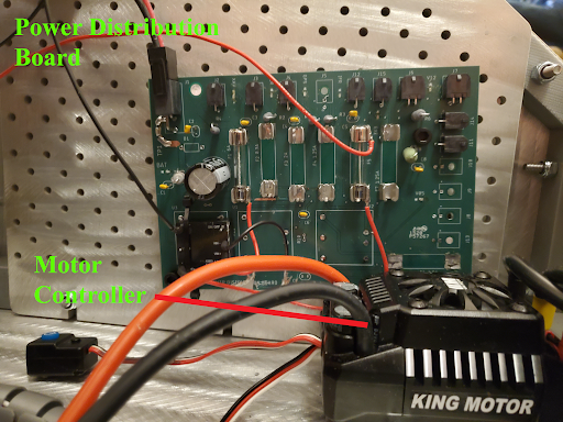
The design of our Power Distribution Board (PDB) has been completed, and we are sending it off for final review before manufacturing. This component will be integral for us to supply correct voltage and current to our array of sensing, actuation, and computing devices.
March 28th, 2020
With all of our 3D-printed components successfully manufactured, we have moved onto assembling our electronics enclosure. We are about 40% of the way completed with the assembly, and currently the fitment of components has given us no issues.
April 3rd, 2020
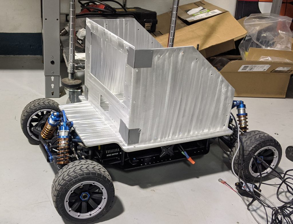
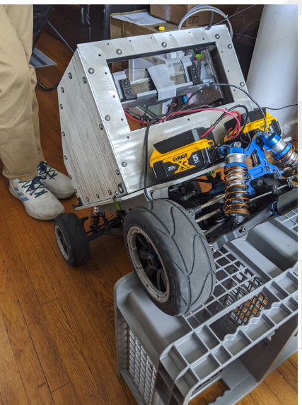
The car was partially assembled with the minimum necessary hardware needed for some shakedown testing today. This was done to just get a general feel for how the servo and DC motor response would be with the the additional weight and how the mounting and enclosure would hold up during testing. The vehicle can be seen here during testing:
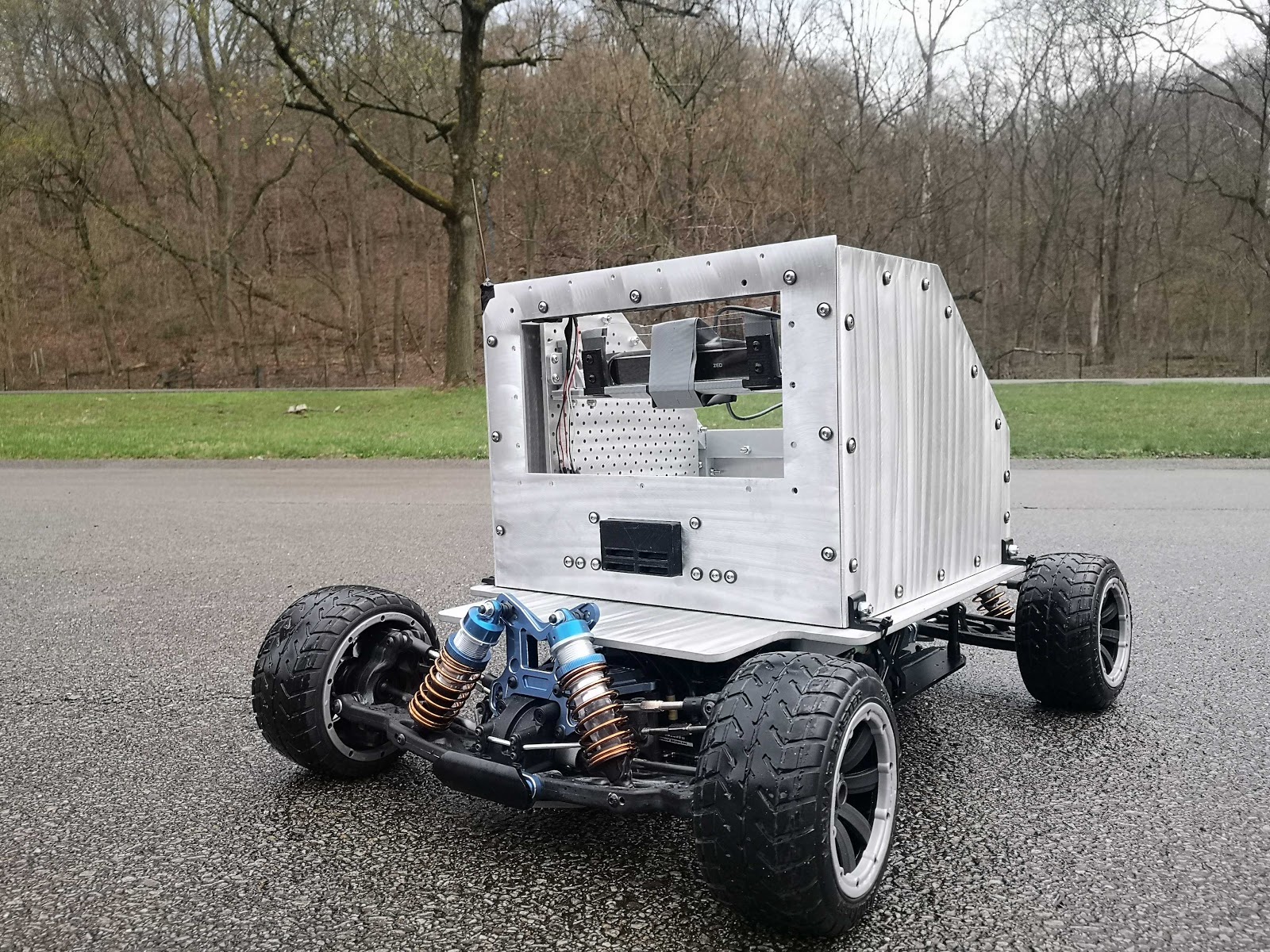
During this testing, it was noticed that the steering response was very slow, and sometimes it would stop all together. The cause is currently unknown, but the vehicle weight is a potential factor that could exacerbate the issue by putting too much load on the tires, which would require more torque from the servo to steer.
April 8th, 2020
The issue mentioned in the last update was solved this week. The source was found to be poor connections between the servo and the receiver, since multiple jumper wires were chained together to get the required length. Since this was just a simple prototype to test the electronics, it was going to be changed in the future anyways, so we went ahead and constructed the new wiring harness to mitigate this issue, which resulted in much more responsive steering control.
April 16th, 2020
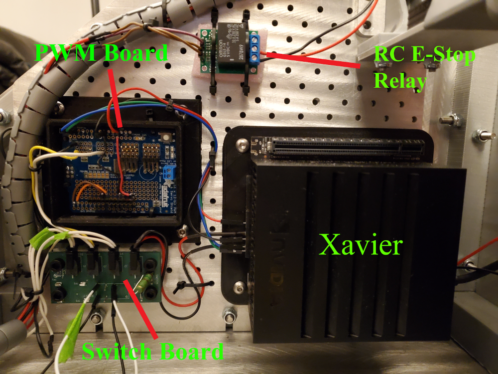
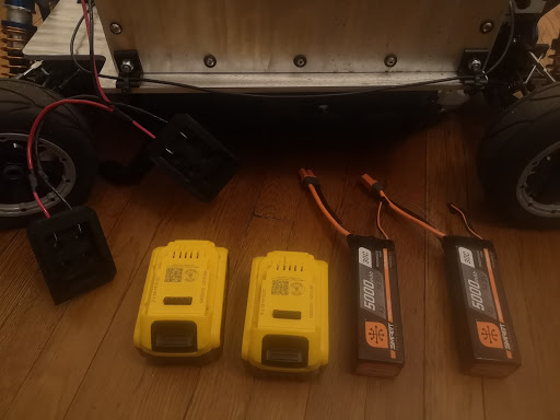
Today we finished the wiring on the platform, with progress being displayed in the images below:
April 21st, 2020
Over the past few days we have been focusing on setting up software to log and stream data from our RTK GPS and IMU devices. After getting the software set up, we needed to calibrate them. We first calibrated the GPS at Highland Park, since we required an open area where the base station could get adequate access to satellites.
To calibrate the IMU we changed the orientation of the vehicle with the IMU mounted and recorded its readings. With data logged from both of these calibration sessions, we can now make sure they are aligned when performing the vehicle localization calculations.
April 26th, 2020
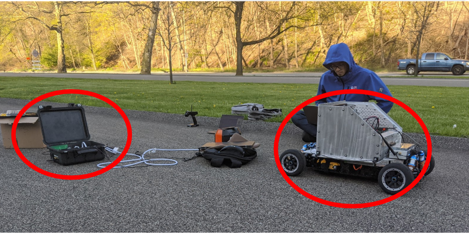
Today we went out on our final physical testing session for the spring semester, which was at Highland Park. The image below is of the platform with all of the most recent progress made displayed.
Fall 2020 Development
Since much of the fabrication was complete in the spring there were only four main areas where we were still working on the platform in the fall. These were a new set of PCBs, custom encoders, fabricating the lid and window, and 3D printing mounts for various items.
September 20th, 2020
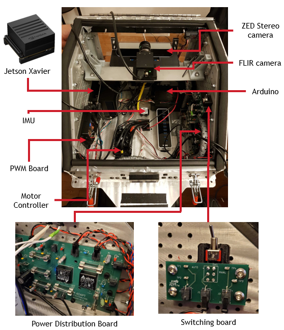
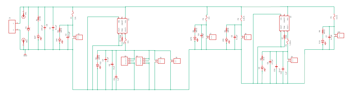
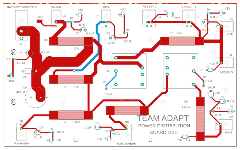
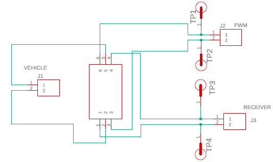
Near the end of the spring semester, we, unfortunately, blew a portion of the power distribution board (PDB) making it no longer usable in the long-term. Over the summer we redesigned the PDB, as well as the switch board, and underwent another round of reviews before placing the order. The schematics and images of the boards are shown below, with the PDB being the first two and the switch board the last two. Some general improvements were made as well. One was reducing the number of connectors, since we were more certain about what the system would actually need. Another was spacing out the fuses to make them easier to replace. The switch board was also reduced to contain only a manual switch for toggling the robot between manual and autonomous mode.
September 25th, 2020
The final manufacturing task, the window, and lid required using the machine shop’s CNC machine to cut Lexan. It was imperative that the window be clear of scratches so we took extra care to keep it protected and made a spare in case one of them had a scratch or got one. At the same time, we also cut the polarized filter holders for the ZED camera. These also needed to be scratch-free. The lid mattered less, but it did need to be bent in order to fit the form of the enclosure. For this, we cut a flattened version of the lid from the Lexan, then used a heat bar to soften the material and bent it to form. The bending process was repeated again for the joint near the latches.
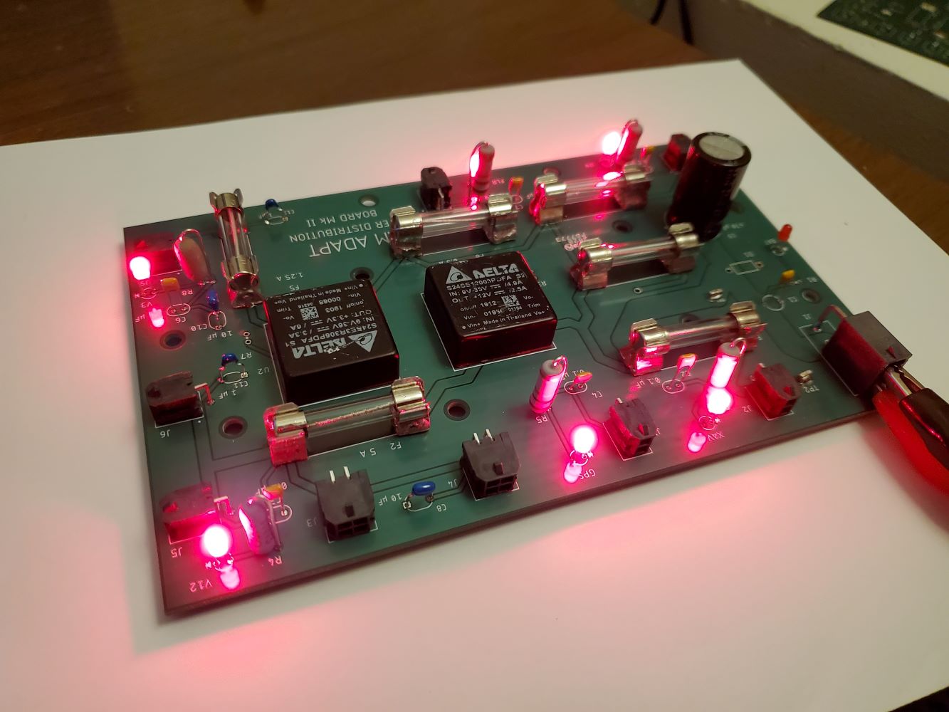
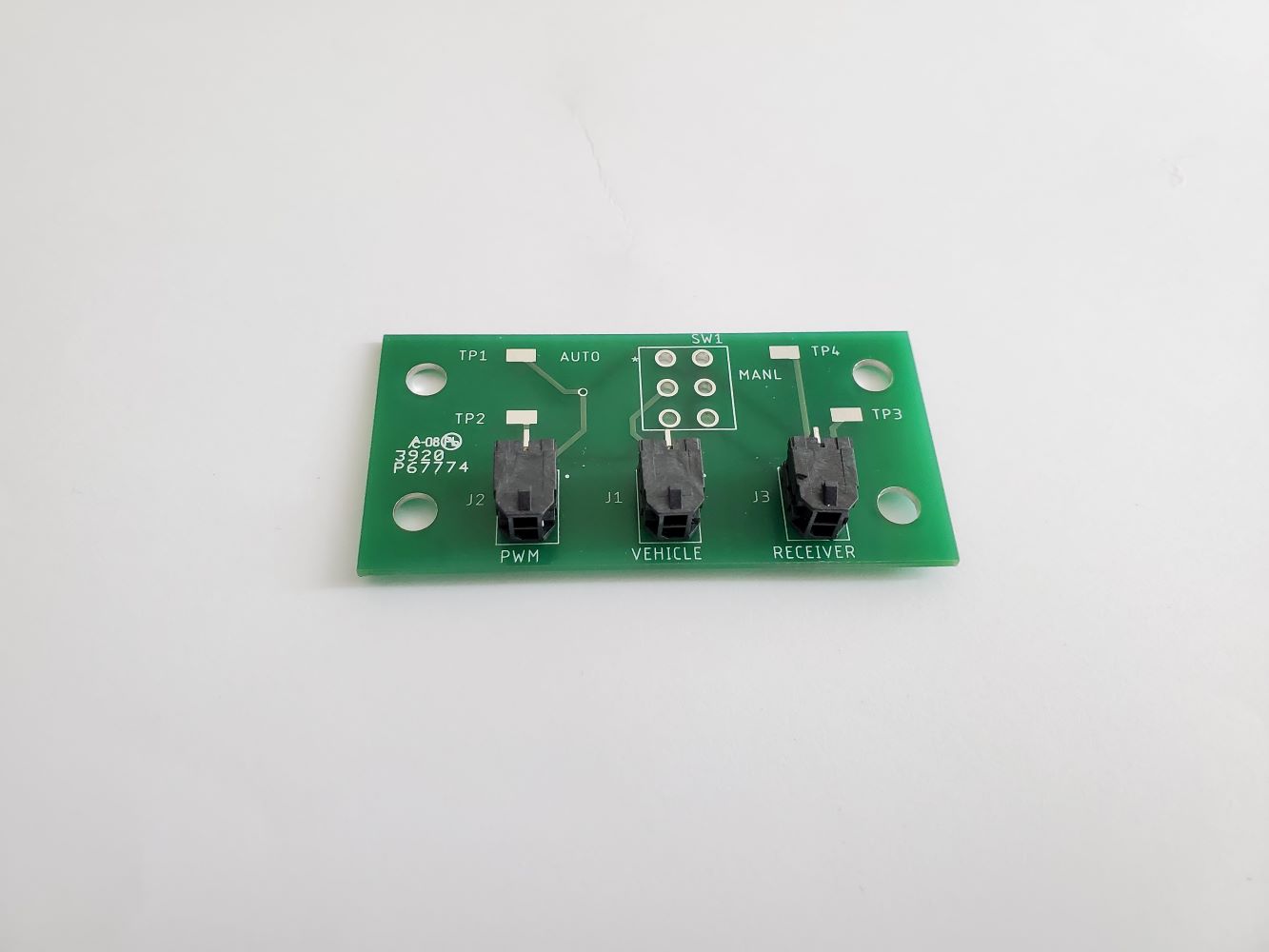
October 1st, 2020
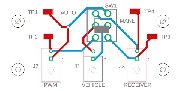
Once the boards arrived, we worked to get all of the components soldered on while testing each connection along the way. The power distribution board (top image) went together without any issues. We found on the switch board, the second image below, that the holes were not large enough for the pegs on the manual switch. What we needed to do was solder short cables from the board to the switch and also worked on a 3D printed mount to hold them rigidly together as well as act as the mount to the side cheese plate.
October 20th, 2020
Before the start of the semester, we began work on a set of custom encoders. The main reasons for developing them was that we needed an encoder that we could mount without disassembling the drive system of the vehicle, and also one that we could feasibly seal and keep water from getting in, and no options we found met these criteria. Planning analysis for the system can be found here.
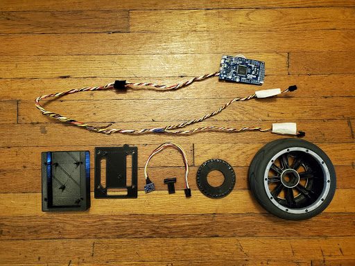
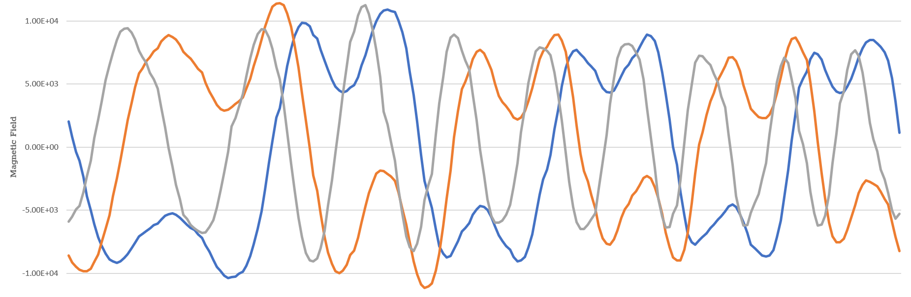
Components for the encoder are shown in the first image below. On the top are the Arduino and cable harness. The items on the bottom, from left to right, are the Arduino case, Arduino case lid, magnetometer, magnetometer mount, magnet ring, and wheel. The custom encoder is comprised of a set of thirty-six cube magnets which are glued into a 3D printed ring. Adjacent magnets are oriented 90° relative to each other to create variations in magnetic field that a magnetometer can detect. The rings are attached to the insides of the front wheel hubs. Magnetometers are placed inside 3D printed mounts that are attached to uprights next to the wheel hubs and placed as close as possible to the ring of magnets. Cable harnesses are made for I2C signals between the magnetometers and an Arduino Due. The signal cables are twisted to reduce noise and modularized using connectors. The raw magnetometer signals when the wheels are turning are shown in the second figure below. The magnetometer measures the magnetic field of three axes, and each wave corresponds to one axis, as depicted by different colors in the graph. A circular buffer is used to store the magnetic field values within a small sliding window. The Arduino processes these signals and converts them to velocities by counting the number of transitions between peaks and troughs of the signal. The two horizontal lines on the plot are the upper and lower threshold values for the blue and red curves to check whether transitions are valid. The Arduino also resets itself or power cycles the magnetometers when they fail. The velocities are then sent to the Xavier via serial communication, where they are parsed and passed to the localization pipeline.

The custom encoders required significant work in order to ensure they were operating optimally. The first of these was finding the mounting location for the magnetometer where it would get the best possible signal from the magnet ring. For this, a variety of locations along and twists relative to the upright were checked. For each of these, the signal output was observed and the location with the strongest signals closest to a sinusoid was chosen. The image below presents an example of a location where the signal took the shape of a series of M’s and W’s as compared to the signal taken from another location shown in the image above. In the image below the blue and gold lines represent x and y axes data, which are the components used for measuring ticks. These undesirable signal features increased the chance of misreading a transition from peak to trough or vice versa. Once the magnetometer was fixed in place, these same signal readouts were used to place the thresholds to provide the most robust tick readings. Finally, all of this was verified by pushing the vehicle for one revolution of its wheels and comparing the number of ticks measured by the custom encoder with the number of expected ticks per revolution.
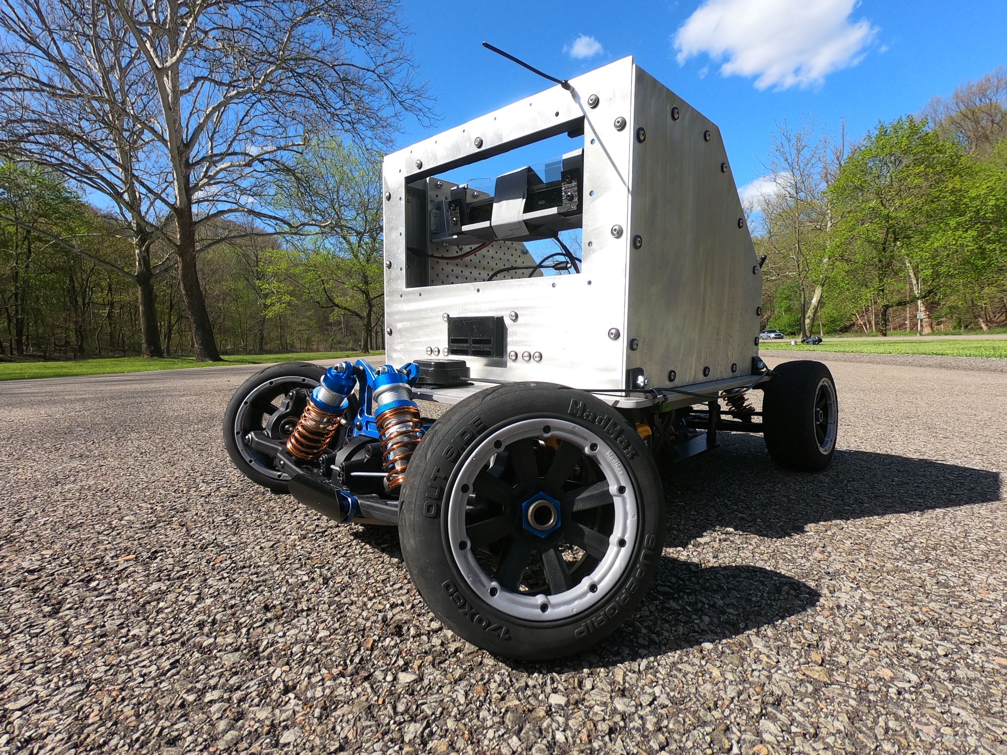
October 30th, 2020
With all components in hand, we assembled the vehicle throughout September and October into the final version seen below.