Demonstration #1
For Demonstration #1 of the Spring Validation Demonstration (SVD), the terrain comprehension subsystem was evaluated against M.P.1 and M.P.3., which stipulate the accuracy of the segmentation of road and puddle, respectively. For road, 96.5% of frames had an IoU greater than85%. For puddle, 38.9% of frames had an IoU greater than 85%. While not a performance require-ment evaluated for SVD, the average IoU of road across all frames was 95.2%, and the averageIoU of puddle was 73.9% across all frames. Figure 1 shows the frame segmented into road and puddle.
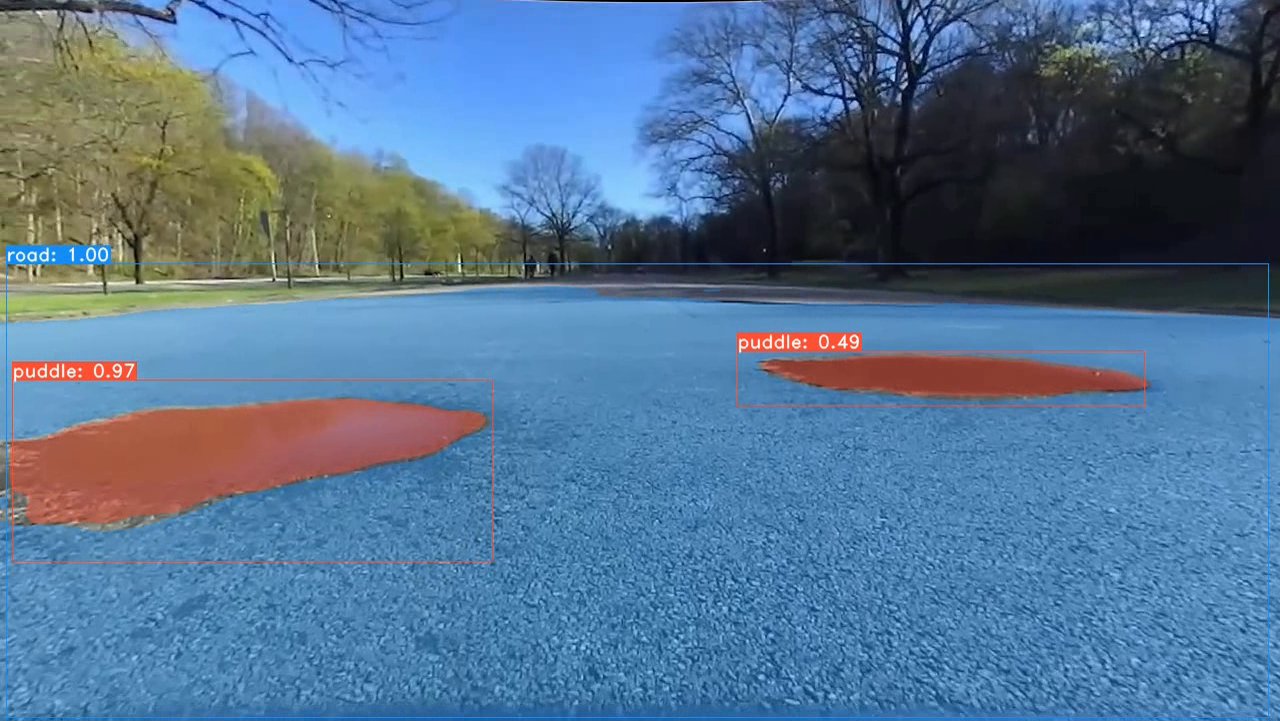
Figure 1. Performance of the perception subsystem on a single frame
- M.P.1. – road segmentation IoU greater than 85% for at least 85% of frames ✅
- M.P.3. – puddle segmentation IoU greater than 85% for at least 85% of frames ⛔
Demonstration #2
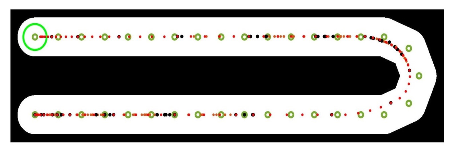
Figure 2. Curvilinear path following in simulation
The trajectory was then passed to the controller within the simulation, and after the car traversed the map, the following performance plots in Figures 3 and 4 were generated.
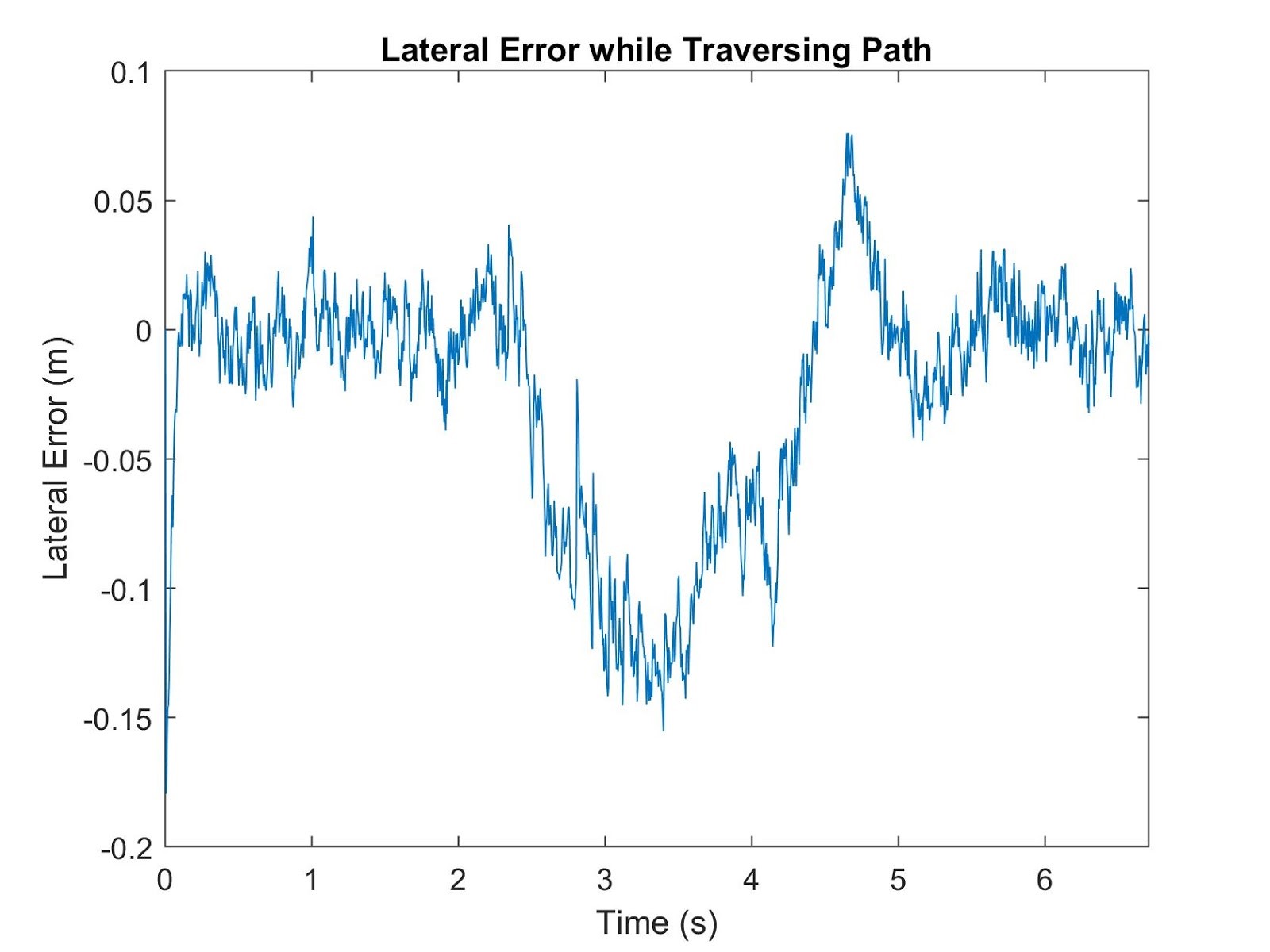
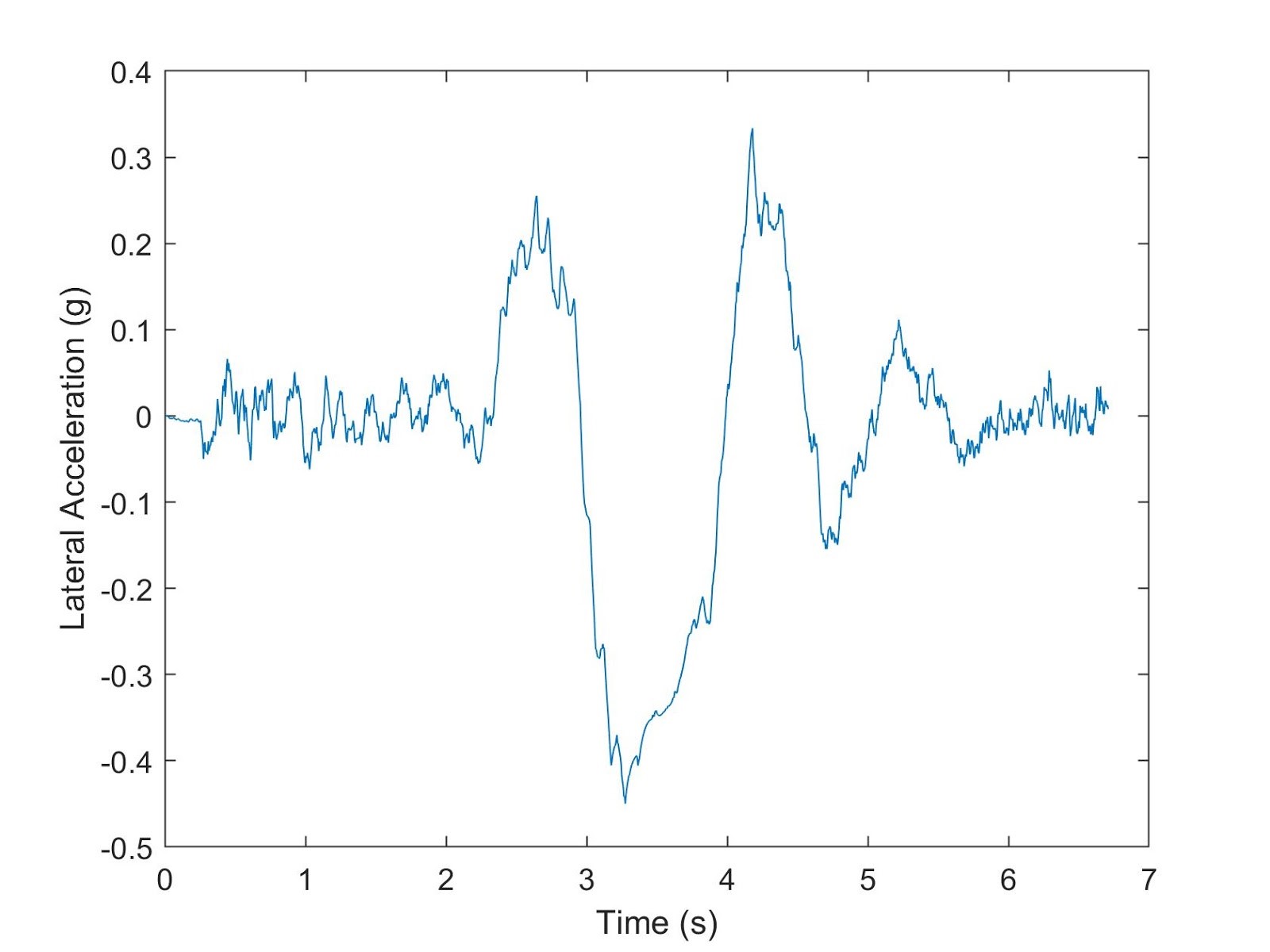
As shown in Figure 3, the lateral error remains below 0.15m throughout the simulation and only briefly overshoots before returning to a low tracking error after the U-turn. The lateral acceleration signal throughout the simulation stays below 0.5g for the entirety of the simulation and does not exhibit any erratic jumps as displayed in Figure 4. The lateral GRMS was also calculated to be below 0.05. This same trajectory was then passed to the onboard computer for demonstrating real-world tracking. Due to issues with sensor calibration and state estimation, the system was unable to execute the trajectory for the SVD. As such, only requirements M.P.5., M.P.8., M.N.2., and M.N.4.were fully achieved, with M.P.8. and M.N.2. achieved in simulation, and M.P.6. not achieved.
- M.P.5. – capable of curvilinear motion planning ✅
- M.P.6. – real-time motion controls (greater than or equal to 55 Hz) ⛔
- M.P.8. – less than 0.75 m from waypoints at all times
- Simulation ✅
- On-Robot ⛔
- M.N.2. – less than 1.47 grms lateral acceleration
- Simulation ✅
- On-Robot ⛔
- M.N.4. – vehicle runs without external cables ✅
Demonstration #3
Demonstration #3 consisted of a 30m straight-away with randomly located puddles of different radii, designed to show the system’s ability to perform terrain-aware planning. Figure 5 shows the map and generated trajectory, starting from the left and ending at the goal on the right.

Figure 5. Terrain aware path following in simulation
From Figure 6 it is apparent that the vehicle slows down when approaching puddles and speeds up again after driving through. This follows from the trajectory in Figure 5 where the density of red dots correlates with intended speed, such that higher density sections are slower.This validates the ability of the system to perform terrain-aware planning followed by trajectory tracking. The sensor issues that prevented physical robot trajectory tracking during Demonstration#2 also prevented this demo from occurring on-robot. As such, requirement M.P.5. was met in simulation but not proven in the real-world, and M.P.6. was not achieved. Open loop control was achieved, which validated requirement M.N.4.
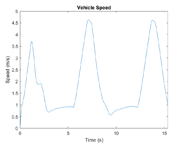
Figure 6. Plot of vehicle speed during the simulation of Demonstration 3
- M.P.5. – slows down for puddles
- Simulation ✅
- On-Robot ⛔
- M.P.6. – real-time motion controls (greater than or equal to 55Hz) ⛔
- M.N.4. – vehicle runs without external cables ✅
