Thursday, February 20, 2020 – Jackal Simulation Setup and Mapping
We demonstrated a Jackal simulation with basic mapping functionalities. Most importantly, by implementing the Jackal simulation within ROS stack, we verified our designed functional architecture is achievable and compatible with Jackal subsystem, which also does not require much low-level development.
The mapping, localization, navigation and obstacle detection are all implemented in ROS framework. Based on the given model with URDF, laser scan, controller and motion planner, we integrate LIDAR model to Jackal robot in Gazebo, replace laser scanner node with Velodyne node and let the robot generate PointCloud to replace 2D scan in each state and reroute the added PointCloud message to ROS gmapping package for SLAM. A complete rqt graph showing the relationship between nodes and topics are shown in Figure 1 below.

Figure 1. Jackal Simulation RQT Graph
A frame from the simulation is shown in Figure 2, with Gazebo world on the left and perception simulation on the right.
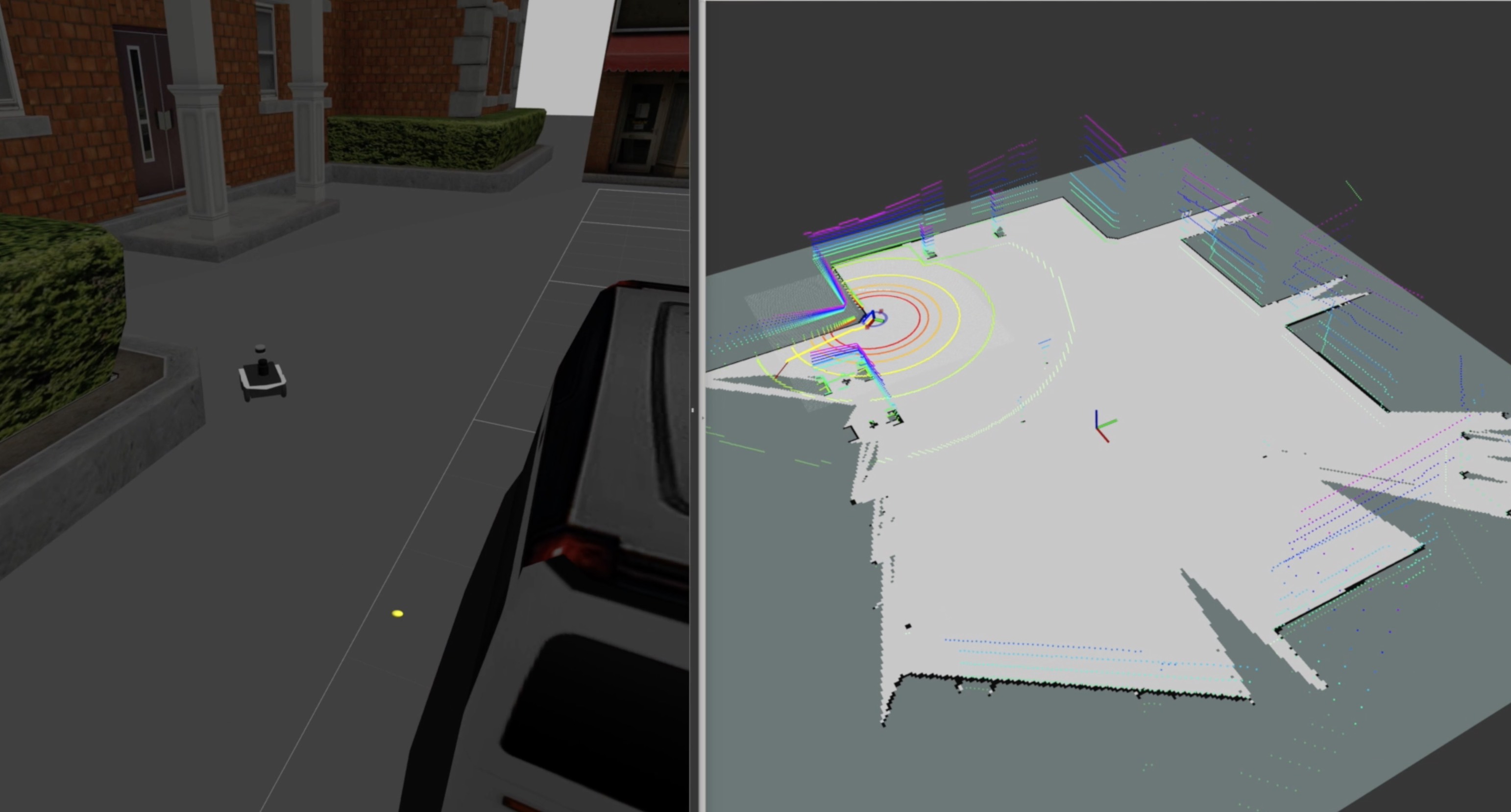
Figure 2. Jackal ROS simulation
Monday, March 2, 2020
A new algorithm for optimal landing point selection for the UGV subsystem was pushed out. The pseudo-code is shown below.
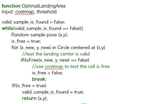
The key idea behind the algorithm was that we check whether there is a large enough circle existing, which was centered at a position randomly sampled from the given map. The radius circle had to reach the threshold for safe landing. The sampling part was triggered by RRT, or RRT-connect algorithm, in order to speed the process up. After that, since the map was an occupancy grid, we had to discretize the circle to check whether each point inside the circle is valid. In order words, the cell is free of obstacles. If we found a valid sample point, we would use this point for the UGV to navigate, which helped update the map for the next step.
Thursday, March 5, 2020
Today, we presented a proposed testing plan for the final goal we wanted to achieve in the fall 2020 semester. The importance of this simulation test set is that it embodies the functional requirements into simulated test cases that we can visualize. Therefore, when conducting UGV technical development, we can always be able to reflect on the test cases and ensure what we are developing conforms with our goal.
The simulation world had two types of obstacles — static and dynamic. As shown in figure 3, the static obstacles are the white-orange roadblocks, and the dynamic obstacles are the dark gray blocks. The static obstacles were designed to simulate the map — such as google map — builtin to the robot, while the dynamic obstacles were designed to simulate unpredictable changes occurred at certain map area (ie. parked cars, construction zones). In our simulation, the UGV would first roam around the world with only static obstacles so that it could build a map. The map would then be processed by an algorithm to select potential feasible landing areas. From our map, the algorithm would output three landing area candidates, corresponding to the areas bounded by blue, green, and cyan lanes in Figure 3.
The UGV would first roam to the area bounded by blue lanes and enter our first test case, without knowing the dynamic obstacles. As dynamic obstacles appeared, the UGV would remap the area. Based on the perception from UGV’s onboard LIDAR, it would conclude that this area would not be feasible for landing due to the compact occupied spaces remaining. Then the UGV would head to the green area, where there was an unoccupied area large enough for the UGV to characterize as “feasible for landing” (the area underneath the tree). In this test case, we wanted to let the UAV’s perception to take action and inform the UGV about the environment. As the UAV perceived the tree and characterized this condition as “infeasible for landing”, the UGV would be informed with this information. Lastly, the UGV would roam to the area bounded by cyan lanes. The last test case was a fully opened area without any dynamic obstacles, the system should be able to judge it as a feasible landing condition, and the following landing motion planner would be then executed.
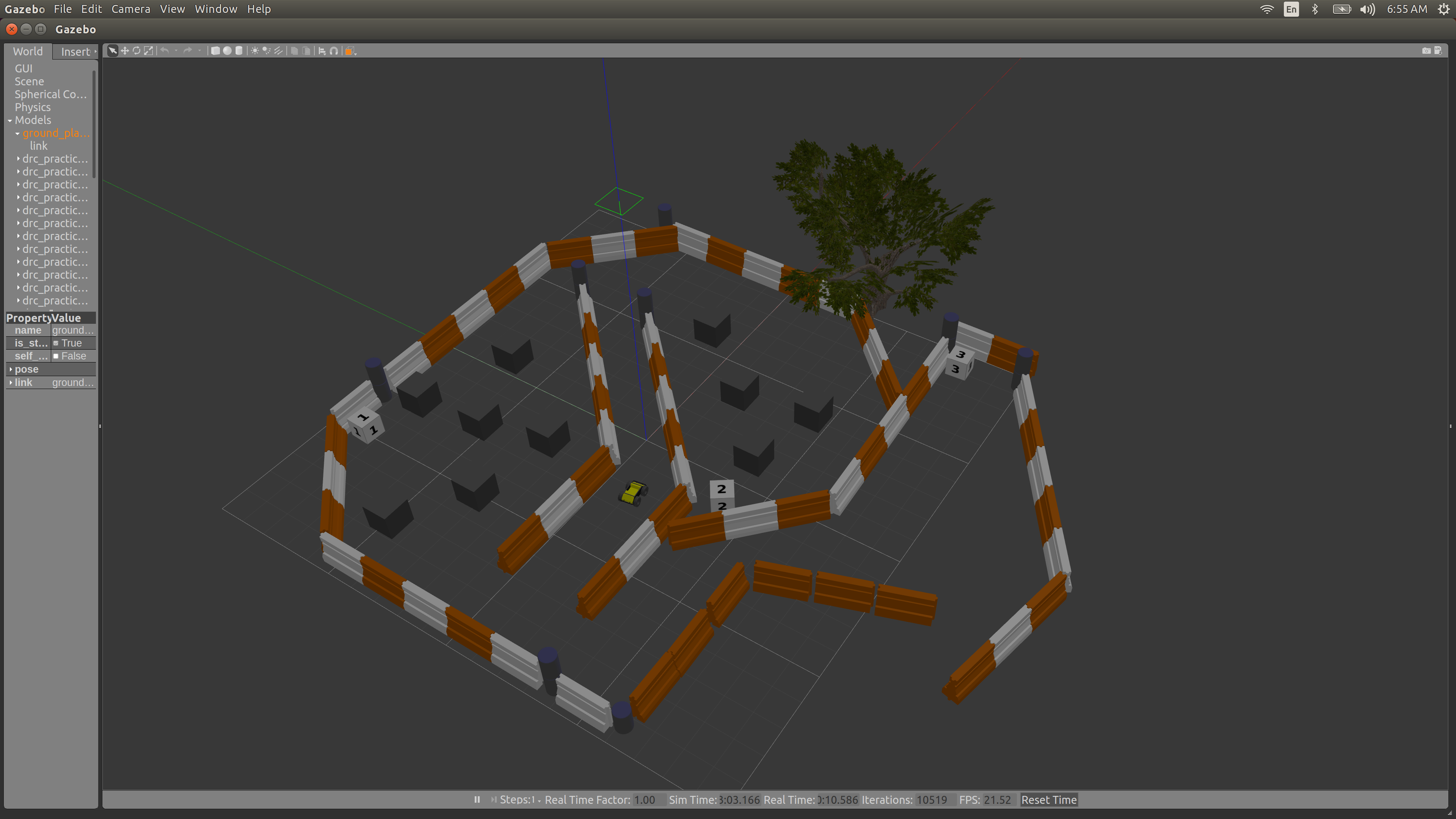
Figure 3. Refined Jackal World with 3 Test Cases
Monday, March 23, 2020
Today is the debut of our UGV waypoint following feature, which employs the actionlib to create a MoveBaseClient which sends the goal. In reality, the call to ac.sendGoal will actually push the goal out over the wire to the move_base node for processing. Under this circumstance, UGV could perform several tasks of path planning with only one command. So far, by combining mapping, optimal landing point selection, and waypoint following, the entire pipeline of UGV simulated automation was completed. With a pre-built map, the UGV could compute the optimal landing point within the map. Then the optimal landing point was sent to the UGV as a target waypoint, which then trigger low-level navigation stack to drive the UGV to the goal location. Along the way, the map could be constantly updated by UGV, since there might be some additional dynamic obstacles that did not appear in the scene when UGV was building the last map version. By completing this feature, we could shift our focus from software simulation to hardware implementation.
Wednesday, March 25, 2020
Due to the COVID19 outbreak, we temporarily lost the access to Jackal UGV hardware. Instead we shifted our development focus to landing platform hardware design and validation. Today, we kicked off our first CAD prototype of landing module as shown in Figure 4.

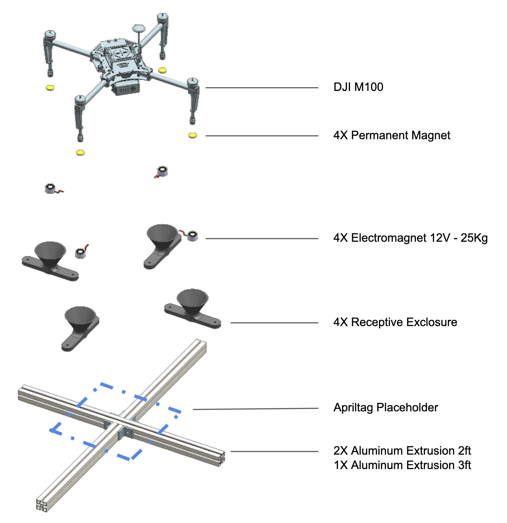
Figure 4. Landing Platform Overview
We would mount a permanent magnet to each feet of the drone; the additional weight mounted to the drone would be very minimal and we expected no interference on flight mobility. The landing platform, which would be mounted onto UGV in fall semester, was consisted of a cross frame built of Aluminum extrusion, and 4 receptor modules, which included receptive enclosures and electromagnets. Specifically, we left a 40x40cm square area on the aluminum base frame to fit in Apriltag for landing. This design emphasizes quick assembly and testing. All the materials could be directly acquired from either McMaster and Amazon.
Thursday, April 2, 2020
Four enclosure modules were printed. We conducted a fit-check with the electromagnet module, which is proved to be successful. The next step was to conduct various engineering validation tests, and to improve the design based on the test results.

Figure 5. Landing Module 3D printed
Monday, September 28, 2020
We designed and implemented the UGV planner to find a valid landing point in a 10m×10m space with obstacles. The UGV used LiDAR point cloud to identify obstacles. After downsampling and segmentation, the UGV will know the distance of the nearest obstacle. We tested in Gazebo, with regular-shaped obstacles, and the UGV was able to find a landing point within several minutes.

Figure 6. UGV planner pipeline

Figure 7. Gazebo environment to test UGV
Wednesday, October 14, 2020
We conducted UGV field tests on mapping and localization. The LiDAR was working properly, but there were some problems with system initialization.
Figure 8. LiDAR point cloud in rviz
Figure 9. UGV field test
We also finished the complete assembly hardware work on the UGV, and fully integrated the landing module onto it.

Figure 10. Updated landing modeule design
Friday, October 23, 2020
We have successfully tested the mapping and localization part and navigation with the odometry. YThe accuracy is within 0.5m based on the odometry.

Figure 11. Navigation test
We made a major update in hardware. We first lowered the mounting height of the landing receptor, reducing from 2 ft to 1 ft elevated from the UGV top platform. Additionally, we presented a new paperboard platform, with aluminum frames supported underneath. This new design will largely improve the safety for both the UAV and UGV in a failed landing case: the UAV will sit on the paperboard if it failed to land onto the receptor, rather than simply crashing onto the ground. This additional board is light-weighted, and easy to arm and disarm.

Figure 12. Landing module
Tuesday, November 10, 2020
For the UGV, we have successfully tested the obstacle avoidance functionality. We can see in this video that the UGV can find a valid landing point while avoiding obstacles. The final FVD will have a similar setup as this field test but at a larger scale of 10m by 10m. We have also worked on the GPS. Initially we wanted to use the original Jackal GPS module, but the signal is unstable during our fields tests. We therefore decided to switch to RTK, which will give more stable and accurate results.

Figure 13. UGV testing environment with cardboard boxes as obstacles
Wednesday, November 18, 2020
We have done the final testing for UGV before the FVD. We have tested the mapping and localization, navigation and obstacle avoidance. Fig.14 shows the testing environment we have set up.
The average error is less than 0.3 m, which is acceptable. At the meantime, it actually also tested the navigation and the obstacle avoidance function. There was some problems with the white board on the jackal during the navigation, like hitting the obstacles. To solve it, we tuned the parameters of the size of the UGV from 0.4m x 0.4 to 1m x 1m and also changed the buffer between the UGV and the obstacles to 0.1m.
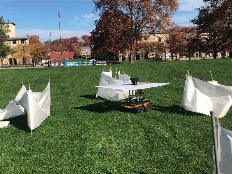
Figure 14. UGV testing environment