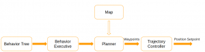
Planning Subsystem
The planning subsystem is responsible for generating the feasible maneuver and trajectory for the UAV.
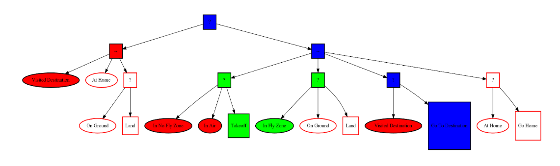
Behavior Tree and Behavior Executive
For high level decision making, we employ the behavior tree first popularized by the video game Halo. The tree is made up of execution nodes, control flow nodes, and decorator nodes. Action nodes and condition nodes are the two types of execution nodes. These nodes are where the state of the system is checked and actions are performed. A condition node returns either SUCCESS or FAILURE to indicate what the state of some part of the system is. For example, an “On Ground” condition node could indicate whether or not the robot is on the ground. These are shown as the oval-shaped nodes in the figure above. Green ones indicate SUCCESS, red ones indicate FAILURE. A sample behavior tree can be seen in figure below.
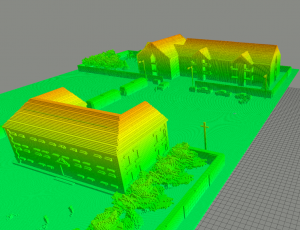
Map
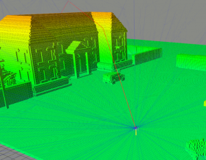
We utilize Octomap for our map representation, which is a efficient 3D occupancy grid mapping approach based on octree. Since we implemented our system in Gazebo simulation for this semester, we use a Gazebo plugin to generate the octomap representation of our designed Gazebo world. The result is shown in figure below. For the next semester as we deploy our software to physical system, we plan on generate the map of our testing area offline by approximating the environment in Gazebo and use the same plugin to build the octomap offline.
Global Planner
The job of global planner is to generate set of waypoints for the drone to follow given the start and goal locations. We are using the RRT* planner in OMPL(Open Motion Planning Library) to generate path. Since OMPL doesn’t support domain-specific implementation, which means we need to have some additional packages to deal with things like workspace representation or customized state space. For workspace representation, octomap representation interface provided by the sponsor allows us to do the state validity and collision checkings in the workspace. For the state space, we implement our customized (x, y, z ,yaw) state space using the CompoundStateSpace object in OMPL. The planning result is shown in figure down below. The blue lines are the entire graph generated by RRT*, and the red line is the solved path.
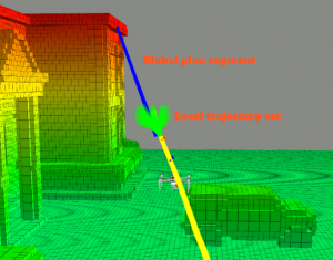
Local Planner
The job of local planner is to generate dynamic feasible trajectory given the global plan, and we use a motion primitives-based planner for our system. This planner is mainly implemented by our sponsor and we only made some minor changes to it. Given the global plan , the local planner will choose the least-cost motion primitive that is not in the collision, and stitch them together to get the actual trajectory. The cost function of each motion primitive is assigned by considering the overall distance between the global plan segment and the closest obstacle distance. The overall result can be shown in figure below. The blue line is the global plan segment, and the green lines are the pregenerated motion primitives. The yellow line is the actual trajectory that local planner generates so for.