Visual Servo
Our sensing subsystem is mainly used for visual servoing, with the package and balcony platform as targets.
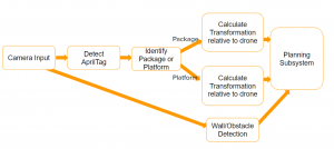
The camera-input takes in the stream of RGB images captured by the camera. It detects the existence of any AprilTags in the image, identifies if it belongs to a package or platform, and calculates and sends the pose transformation information to the planning subsystem. The camera input will also be used to perform simple wall and obstacle detection, which we might utilize the point cloud sensor data type.
As of May of 2020, most of the progress of the visual servo has been in Gazebo simulation, due to the COVID-19 outbreak.
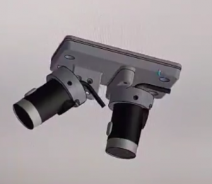
We utilize the realsense_gazebo_plugin package to implement two simulated RealSense D435i cameras, both attached to our simulated drone, one pointing straight down to detect packages, the other pointing 25 degrees forward from the z-axis. When the package is gripped and being transported, the bottom camera will be blocked, thus we need an additional camera for the visual servoing of the platform. The front tilt also helps with the platform servo, since it allows the drone to not be right on top of the AprilTag and risk hitting the eaves.
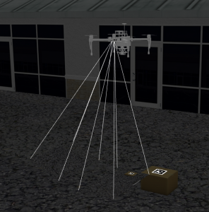
With the transformation from the drone to the AprilTag, we are able to use the global coordinates of the drone to obtain the global coordinate of the package location in every frame where the AprilTag is detected. we publish these coordinates to the navigation subsystem to generate waypoints for the drone to fly directly on top of the package in range to activate the gripper and pick up the package.
Here are the performance statistics of our visual servo function, for both the package servo and platform servo:
| # of tests | # of success | Success Rate | |
| Package |
20 |
20 |
100% |
|
Platform |
20 |
19 |
95% |
Camera
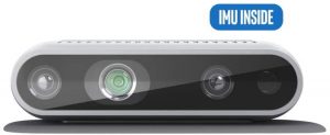
To meet the needs mentioned in the previous section, we decided to use the Intel RealSense Depth Camera D435i, and we are currently only using the RGB sensor functions of this camera. There is also a laser depth sensor and an IMU implemented in the RealSense D435i which we might utilize in the future.
Camera Update
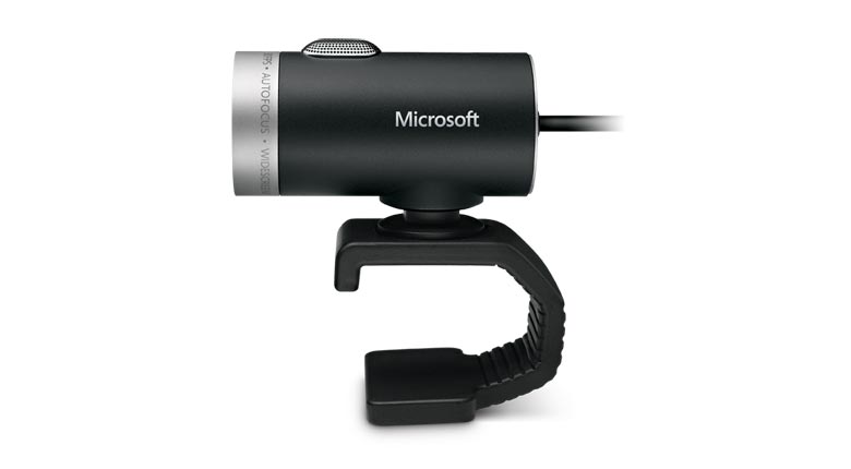
Although the RealSense is a powerful piece of hardware, it has some compatibility issues with our system. The D435i pulls too much current from the system, causing the GPS to shut off. We even switched off all the functions that are not in uses on the ReaslSense (IMU, depth) and it is still drawing too much. Thus, we decided to switch to Microsoft LifeCam, which is a USB webcam with RGB only. After the switch, everything worked fine.
Software Packages
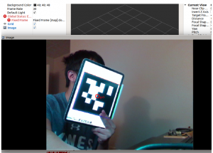
We use the realsense-ros package for the ROS wrapper, which is the driver to receive RealSense sensor data for ROS. The ROS wrapper requires the official RealSense Camera Software Development Kit – librealsense. For the AprilTag tracking, the apriltags_ros package provides the pose transformations of the AprilTag. Below is an image of using all three of these packages to detect an AprilTag using the RealSense Camera, visualized in Rviz.
Mounting Design and Installation
We designed it in Solidworks, and made the front camera angle-adjustable. The connecting peice is 3D printed with PLA, and subsequently installed onto the drone. Below is the original camera mount design for the RealSense D435i.
Below is the CAD drawing screenshot of the new design for Microsoft LifeCam.
Visual Servoing without GPS
In a field test, we found out that the GPS error from the drone is too high for precise pickup, mostly the Z direction’s error. The error was about 0.5 meters, which would have a significant chance of crashing into the ground. As a result, we needed to change our previous visual servoing with the position-based controller to the velocity-based controller as the DJI’s velocity controller is much more accurate.
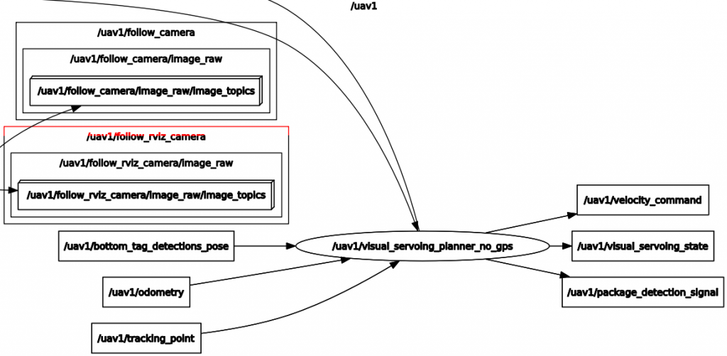
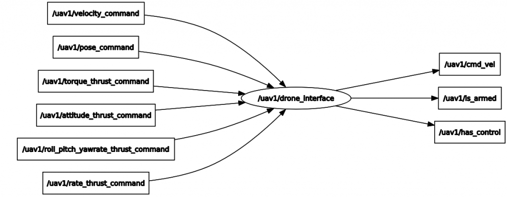
The new visual servoing will only consider the tag’s pose to compute the corresponding velocity and send directly to the drone interface, bypassing the pose controller as in the previous version. With the updated visual servoing, the drone can make a smoother descend as it does not depend on the odometry to navigate.
Visual Servoing Defensive Behavior
With the previously implemented visual servoing without GPS, our drone works well in simulation. However, because we found out that the hertz rate of the camera in the drone is neither stable nor decently fast when unit testing them and that wind could make the April tag out-of-view, I implemented more safety-guard steps within visual servoing to ensure that the drone see the April tag stably before executing the grasping. The updated visual servoing behavior will have several parameters for tuning to adapt to the environment that we will test on.

The diagram above illustrates the drone’s states during the visual servoing process and some of the parameters that would help the robot to grasp the box in harsh environments defensively, specifically:
- maximum_tag_time: The maximum seconds from now that the detection must be within to be considered.
- fly_up_time: The maximum seconds from now that the detection must be within to be considered.
- hover_distance: The z distance above the April tag that the drone needs to fly to.
- minimum_detection_times: The minimum times that the April Tag needs to be seen after the drone reached the point above the April tag.
- dropdown_velocity_z: The dropdown velocity in direction z for the drone to grasp the box
- acceptance_time: The drone must stop dropping down after these seconds.
- acceptance_distance_x: The threshold for the drone to be considered having reached the hovering distance in x direction.
- acceptance_distance_y: The threshold for the drone to be considered having reached the hovering distance in y direction.
- acceptance_distance_z: The threshold for the drone to be considered having reached the hovering distance in z direction.
We defined these parameters to give the flexibility for the team to test the behavior defensively in the real world to avoid any potential crash.