For our robot to explore the garage, navigate safely and park in a free spot, multiple sub-systems run in parallel to achieve the objective. The system kicks into action by sensing its surroundings and registering its environment with respect to a single frame of reference. To estimate its current position in the scene, our system performs simultaneous localization and mapping, thereby registering all information gained about the environment over time into a single map and localizing itself in that map using both current and previous sensor data. In a parallel thread, lane and parking spot detection run to constrain navigation and look for free parking spots, respectively. The navigation stack is responsible for autonomously moving the robot around based on road constraints and desired waypoints. The brain behind exploration comes from the exploration stack, which proposes where to go next to move towards a free spot. Finally, upon successful detection of a parking spot, the parking subsystem closes the system functionality by executing the parking maneuver and parking in the spot.
1. Sensing Subsystem
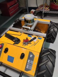
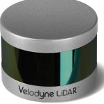
The most basic action of our system is to sense its environment with precision as it is crucial to every subsystem that follows. There are many ways to sense the environment. We base our choice of sensor suite on the SLAM pipeline we are using. We have chosen to use the Husky’s built-in wheel odometry, Intel RealSense d435 and d435i depth cameras, and a Velodyne LiDAR (Puck) for our system. This decision is based on the fact that we are using RTAB map as our SLAM pipeline which expects laser scans, depth images and encoder data as input.

2. SLAM Subsystem
One of our major sponsor requirements is the creation of accurate and low-drift maps online/real-time in our system (M.P.2). This subsystem directly addresses this requirement along with providing a pose estimate of the robot. The sensor stream is input to the system, which outputs a 3D map of the environment along with an estimated localization of the robot.
RTAB supports creation of semi-dense maps incorporating wheel odometry to reduce drift and runs in real-time on a CPU, thus emerging as our choice of SLAM pipeline.
3. Detection Subsystem
One of the assumptions about the garage environment is the presence of a solid lane line to guide navigation of the robot. We will perform lane detection to segment the lane in camera images obtained from the d435. This information will eventually be used in the exploration and navigation stage.
As the robot navigates the garage, there is a need to detect free parking spots in the array of cars. In order to do this, the detection subsystem will also be analyzing images and constantly checking for free spots. To restrict the scope of our system, our demonstration involves marking the free spot with an AprilTag to simplify the detection process. We are intending to use AprilTags as they are easy to detect due to their rich features and uniqueness.
4. Goal generation Subsystem
In a traditional navigation system for an autonomous car, there exists a built-in high-resolution map of the environment in which landmarks are marked. The goal location is chosen on this fully defined map and a path is planned to the goal. However, in our scenario, due to the lack of a prior map of the environment, we need an algorithm to direct the robot on where to go next to search for a spot. This gives rise to the need of an exploration algorithm. In its linguistic sense, exploration refers to moving around the environment to gain more information. In a navigational perspective, it can be viewed as searching for and generating a goal pose in a given partially built map such that the robot obtains maximum new information about the environment from that new pose.
We reproject the lane from images and enforce it on the 2D map to act as constraints. We interpolate the lane line to a new ego-line to generate the 3D goal pose which is forced to a 2D navigation pose provided to the planner.
5. Navigation Subsystem
Given a map, current pose and goal pose of the robot, the navigation subsystem plans a safe and viable path to achieve it. In order to handle the kinodynamic constraints of a car, we are proposing to use the Time elastic band planner in the ROS stack. The planner is also constrained with the lane information to prevent out-of-lane paths from being generated. We use Dijkstra as the global planner and TEB optimizes it to generate the local plan according to the mobility constraints enforced by us.
The generated paths are transferred onto the movebase stack to generate velocity commands. These are passed onto the Husky velocity controller which converts them to wheel velocities.
6. Parking Subsystem
Upon detection of the AprilTag, the control switches to the parking subsystem from the exploration subsystem. A separate subsystem is allotted to the parking maneuver as it consists of a 3 waypoint algorithm to generate a smooth trajectory into the parking spot. This is important because we want to simulate the parking scheme of a car as closely as possible.