Fall Semester Implementation Details (Final Version)
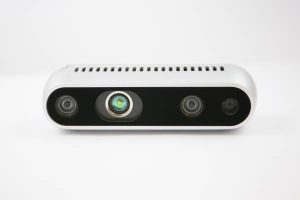
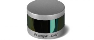
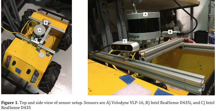
The most basic action of our system is to sense its environment with precision, as every subsystem relies on good sensor data. We chose to use an Intel RealSense D435, and a Velodyne Puck-16 LiDAR for our system, in addition to the built-in wheel encoders on the Husky. The decision to use these sensors was based on the fact that the RTAB SLAM algorithm expects point clouds and wheel odometry as input. We ended up eliminating the encoder input from the RTAB system, but the encoders are still used in the navigation stack for performing accurate PID controls for trajectory tracking. Finally, RGB and depth images from the RealSense D435 were required for lane detection and parking.
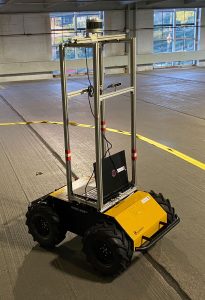
The initial positioning of the sensors on the Husky was based on the relative positioning of LiDAR sensors (usually on the roof) and cameras (usually on the dashboard) on autonomous cars. The actual measurements were scaled down to the size of the Husky. However, after working with data recorded from the sensors at this configuration, we realized that lane lines were not seen effectively from so close to the ground. The height of the sensor configuration was changed to accommodate better views of the lane. The heights were chosen to be close to their actual positions on a car, as mentioned previously. This new sensor configuration gave us much better camera data, allowing us to clearly see longer lane lines in both simulation and hardware.

Spring Semester Implementation Details
Hardware
Milestone for SVD
Our current sensing suite consists of the following sensors:
- Velodyne VLP-16 3D LiDAR
- Intel Realsense D435i (includes IMU)
- Intel Realsense D435
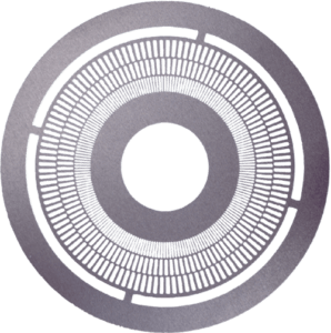
- Husky wheel encoders
- Intel Realsense t265 (purchased but yet to be used)
Prior Work
We have mounted an Intel RealSense D435 camera, an Intel RealSense D435i camera, and a Velodyne VLP-16 3D LiDAR. We are utilizing the wheel encoders of the robot to extract wheel odometry.
We compromised on camera calibration as the outputs generated using default intrinsics provided considerably good data. We measured the relative positioning of each sensor with respect to the robot base frame to generate an accurate URDF model for our robot.
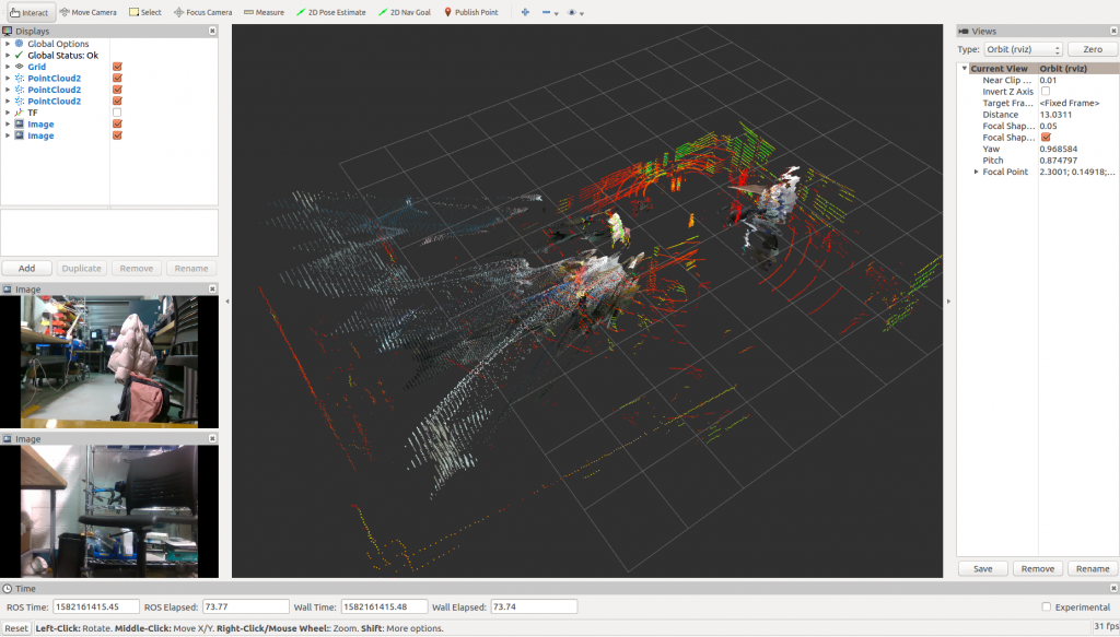
Fig: (Bottom-left)RGB images of the front and rear cameras; (Middle) Point clouds published by both the cameras and the 3D lidar.
Simulation
We developed a parking lot gazebo world to facilitate the prototyping of our algorithms. The size of the gazebo model is of the same scale and measurements of the 3rd floor of the CMU parking lot. We have a custom ground plane to imitate the lane and parking line markings present in the lot. We are able to spawn our custom husky model in the simulated world and publish observed sensor data of this environment over ROS.
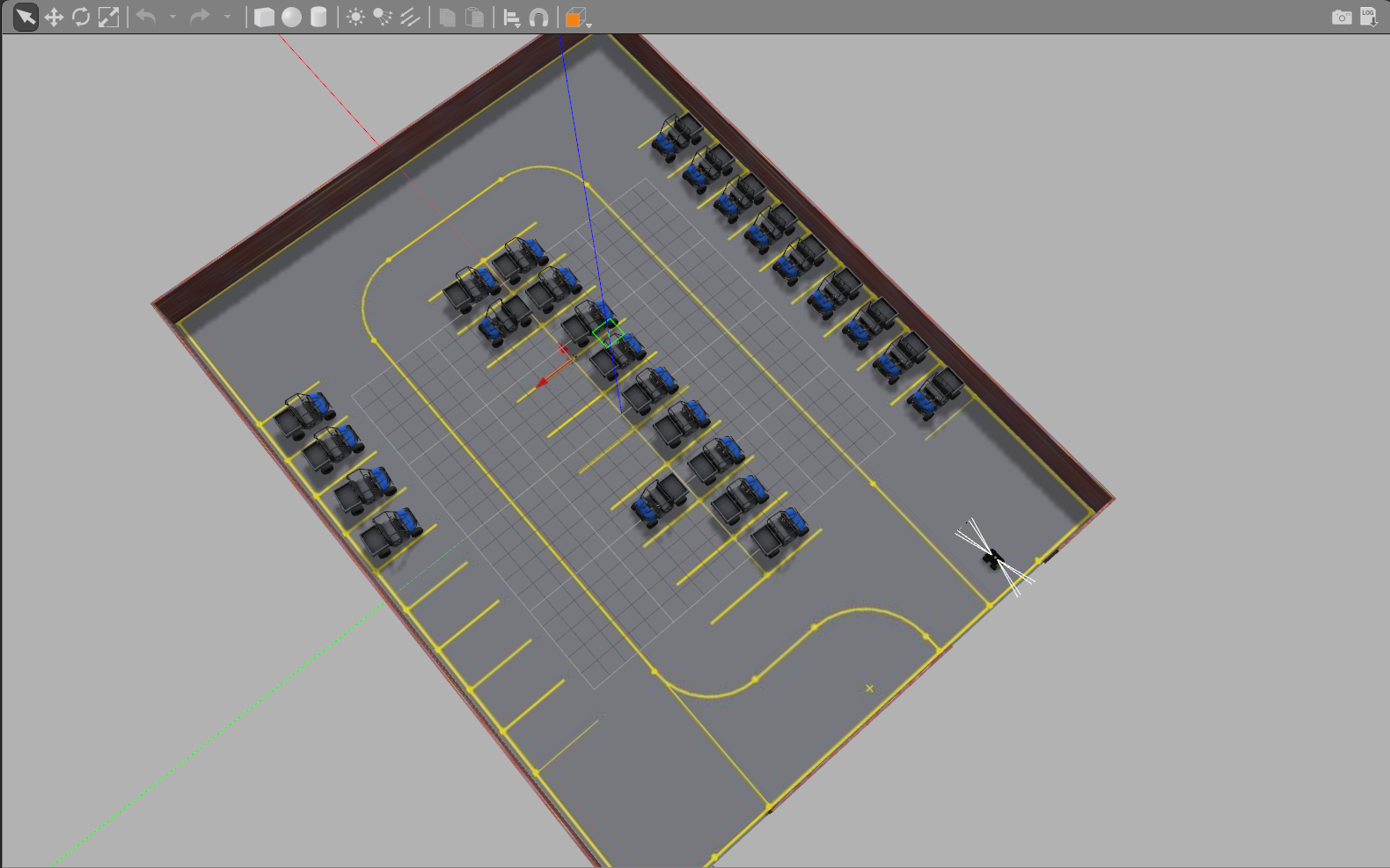
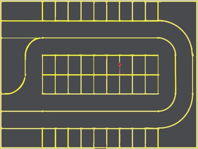
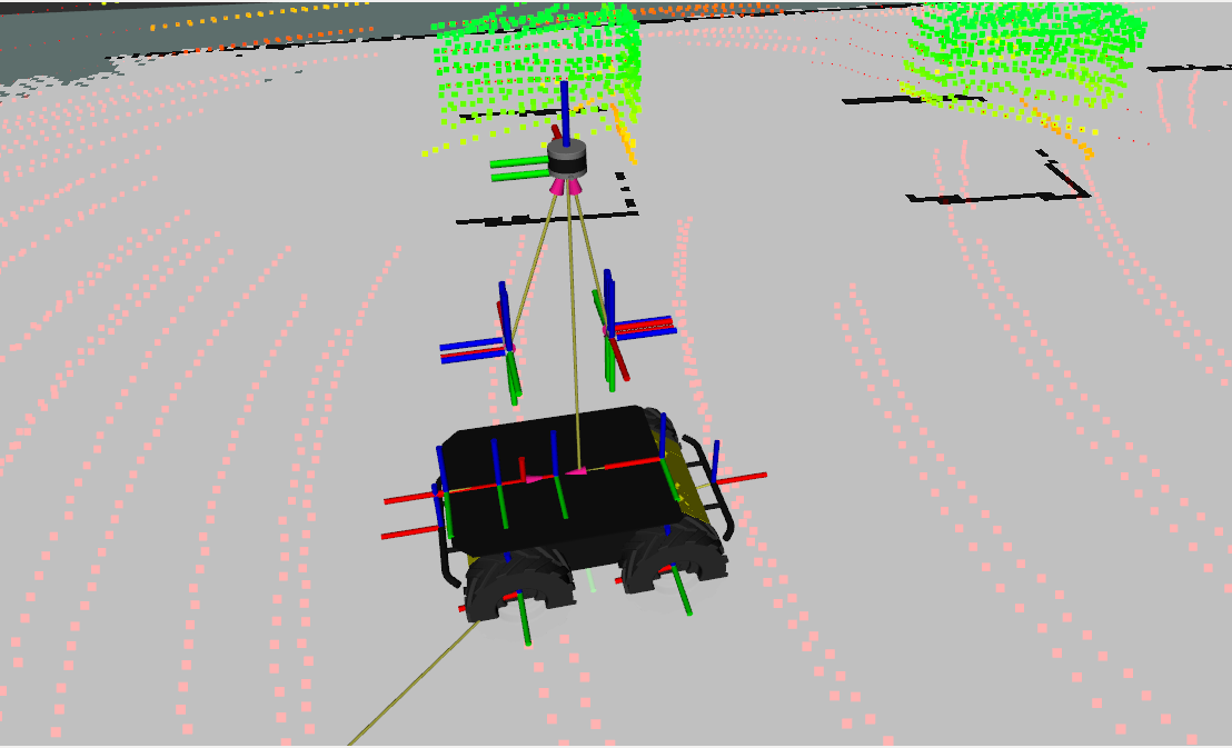
Fig: (Left) Parking lot gazebo world; (Center) Ground plane; (Right) Senor data of the world
We have also added plugins for each sensor so that the corresponding topics are published by simulation.
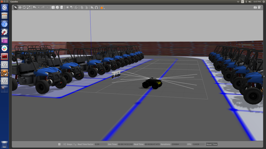
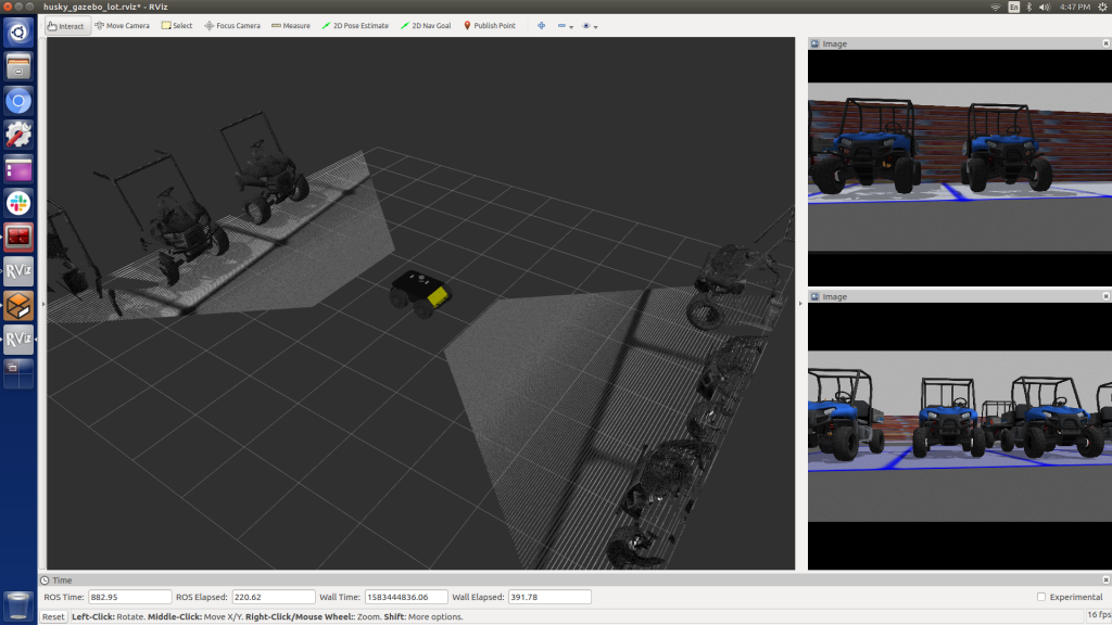
Fig: (Left) Realsense Images and PointClouds over ROS (simulated)
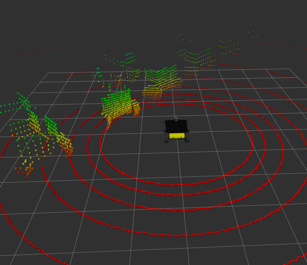
Fig: Simulated LiDAR data