The main power needs of our system are to power the on-board processor, the sensors and the motors. Our test platform is a Clearpath Husky which is equipped with an on-board 24V lead-acid battery source. We run our software stack on an Intel NUC7i5BNH. Our sensors include the Velodyne VLP-16 LiDAR, Intel Realsense d435, and d435i depth cameras.
We have two sources of batteries to power our system. This is due to the fact that the motors draw irregular amounts of currents depending on the type of locomotion. For example, the current draw is considerably higher when the robot rotates in place as compared to moving on a straight path. This behavior is expected as the motors need to provide more torque to overcome sliding friction as compared to rolling friction in order to rotate in place. Our two sources of power are 24V each. One of them is plugged into the Husky electrical system. The other is mounted on the Husky Bay and connects to our custom power distribution board.
The details the power specification of the various components of our system are as follows:
1. Intel NUC – 12 to 19V input – Max current 10A – Max Power 90W (15V 5A_max)
2. Intel Realsense – 5V – 700mA (avg) – 3.5W
3. Velodyne VLP-16 – 9 to 32V input – 12V – 3A (max) – 8W (max)
Taking these values into consideration, our PCB has two independent circuits. The LiDAR circuit taps power from the 12V port present on the robot. We use a high current MOLEX connector for wire-to-board connection. There is a 3A fuse to break the circuit if there’s a current spike. We have added in a single pull double throw switch to turn the LiDAR on and off as there’s no master control switch on neither the power box nor the LiDAR. To increase debugging convenience, we have included test pads and LED indicators. The output line from this circuit is to be connected to the Velodyne power box.
The auxiliary battery in the husky bay is connected to a 24V to 15V DC-DC converter and this 15V line is passed through a 5A fuse to protect the NUC from drawing too much current. We have used similar MOLEX connectors and test pads. The output line from this circuit can be directly connected to the NUC power port via a barrel jack.
Shown below are images of our completed PCB, the PCB integrated into the Husky power system, and the schematic and layout of our PCB designed in Eagle.
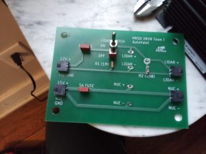
Figure 1: Manufactured PCB
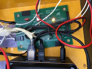
Figure 2. PCB integrated into Husky’s power system
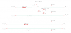
Figure 3: Schematic of our PCB, designed in Eagle
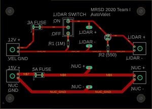
Figure 4: Layout of our PCB, designed in Eagle
Our manufacturer files, schematics/layout and bill of materials together would be useful to understand the electrical system.