Given a lane detected in the 2D image, we need to translate the lane’s position on to the cost map generated by the navigation stack so that the paths generated are within the lane. We take a two-stage approach to implement this:
- Re-project lane line into 3D lane cloud
- Add a “lane” observation source to move_base to register lane on costmap
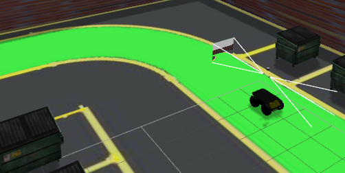
For the re-projection, we first register the depth image onto the RGB image using either RTAB’s depth_registration nodelet (on the husky) or image_view’s depth registration utility (in simulation). We use the RGB camera’s intrinsics to reproject the line onto 3D.
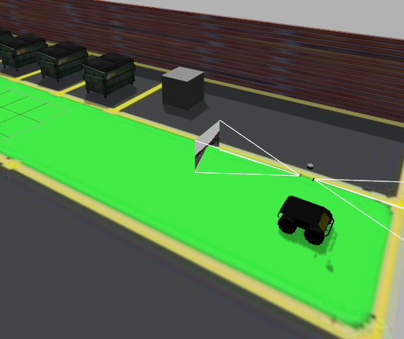
Husky in the gazebo world
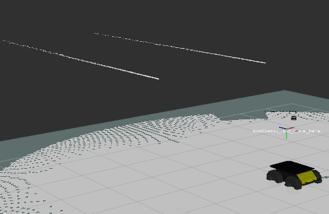
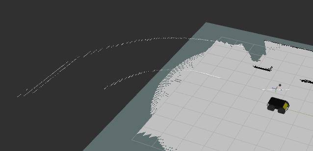
Reprojected lane
Handling turns
Reprojected Turn
Cost map Registration:
We use move_base’s plugin utility to add a fake lane sensor plugin which marks and clears obstacles on the costmap. The observation source was the pointcloud of the lane we reprojected
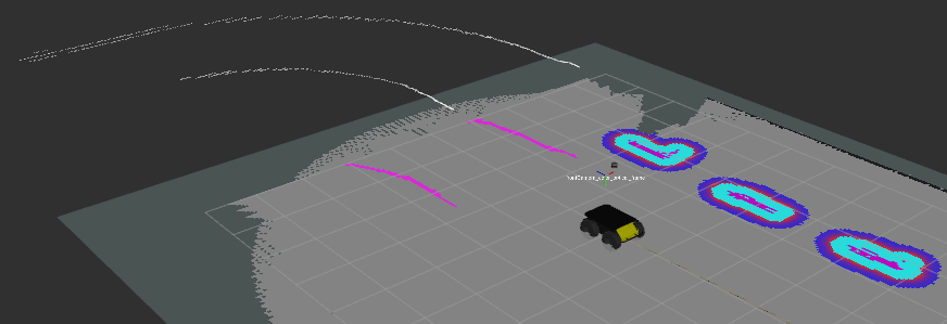
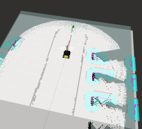
Lane registered on the costmap
Goal Generation:
From this constrained costmap, the initial idea was to generate a goal by searching in front of the robot inside the lane. However, computing the position and yaw from just a local grid costmap with obstacle has proven to be challenging due to the following reasons:
- Finding the center of the lane seems to be quite a challenge as there isn’t a lane line clearly registered on the map at times resulting in broken side lane constraint.
- Even if we find frontiers, choosing the best one seems to be difficult as defining the center of the lane from that local view is hard.
- Generating yaw requires interpolating the tangent of the lane
In order to overcome these, we’re moving ahead with generating the goal using the 3D lane as the prior. The idea is to translate the lane segment’s midpoint by a distance lane_width/2 in the direction normal to the lane and generate the yaw using the line’s direction. We hope this works around curves due to a piece-wise approximation of the curve as a line.
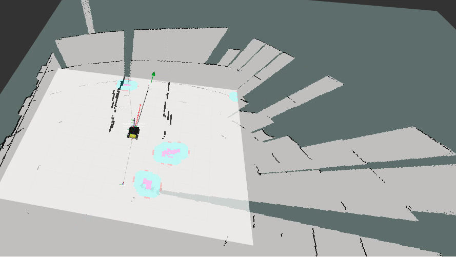
3D lane based goal generation
From our sampled lane line in 2D, we reproject the lane pixels to 3D using the depth map and the camera intrinsics. This forms the center lane line. Extending this along the perpendicular direction, gives us the other lane boundary. These were used in projecting down to costmap to constrain the planner.
We extract another line (called “ego-line”) interpolated at a distance of 0.6*lane width from the center lane. 0.6 instead of 0.5 as it resulted in better performance on real-world experiments due to lower loss of lane line in the FOV of the camera over the turns in the environment. A few variants for generating the goal pose were implemented using this ego-line:
- Mid point of the ego-line cloud and principal direction of the cloud.
- Mid point of the ego-line cloud adjusted into the costmap by the amount of line extended outside the costmap and the principal direction of the cloud
- A tunable distance from the start of the cloud and the principal direction of the cloud.
We ended up using variant 2 as it removed an extra parameter to tune and ensure the generated goals were valid for the planner. The goal generated from the cloud is in 3D. We force it to 2D by setting the pitch and roll to zero and clear the z coordinate also.
Some of our real-world goal poses and simulation poses are shown below: