Spring Semester Implementation Details
Simulation
Milestone For SVD
- Setting ICP/PointToPlane to True (Other option is point to point)
- Voxel Size : 0.2m (Affects runtime/publish rate)
- Grid/RayTracing is set to True (Improves fill-in of the 2D gridmap)
- NeighborLinkRefining is set to True (Optimizes graph based on loop closures)
Prior Work
The algorithm we’re using here is Real-Time Appearance Based Mapping (RTAB-map), primarily because our system uses a similar sensor suite that this algorithm utilizes for SLAM (i.e. a laser scanner, a stereo camera, and a wheel encoder), and that this system will provide us with a semi-dense map, which will fulfill our sponsor requirement. In order to overcome drift, we have set up the SLAM stack to map using point clouds and localize using loop closure from the camera RGB-D images. We fuse the LiDAR and RealSense point clouds to observe the environment. Some crucial parameters that we modified include setting “subscribe_rgbd” to true, “subscribe_scan_cloud” to true, “Grid/RayTracing” to true.
To illustrate more about sensor fusion, there are two things worth bringing up. First, the RGB and the depth image are synchronized with a nodelet called rtabmap_ros/rgbd_sync provided by Rtabmap. The synchronized image is republished as rgbd_image and later fed into Rtabmap. Second, we wrote a new node combining the depth point cloud coming from the front camera and the 3D point cloud coming from the 3D lidar in order to make full use of those data. The combined point cloud message is republished through the ROS network, and we down-project it into a grid map in Rtabmap.
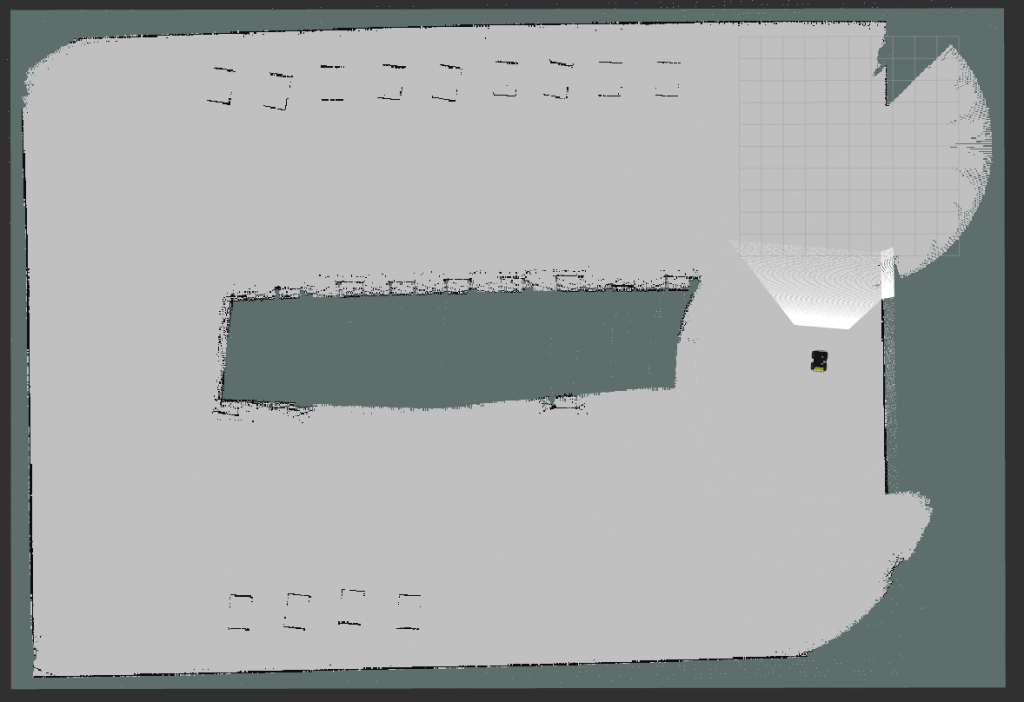
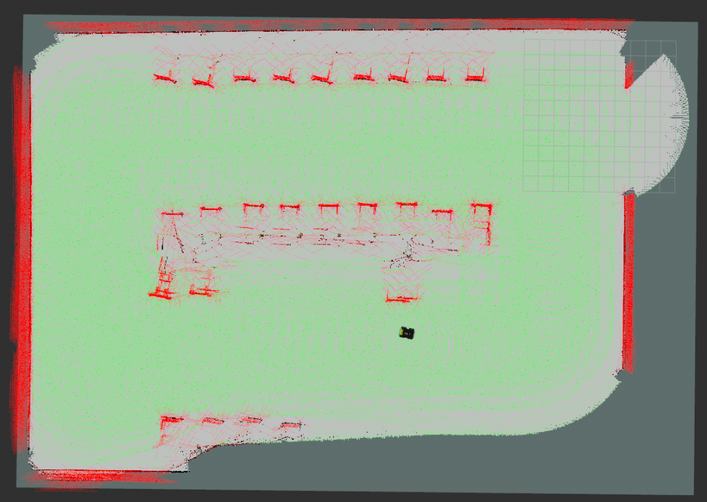
Below are maps we generated using the abovementioned configurations. The obstacles are the pre-occupied cars in the parking lot.
Hardware
We have tested our current SLAM subsystem stack on hardware with our custom PCB embedded. Since we have no access to the campus this semester, the test was done in Subbu’s house. We tele-operate the Husky around the first floor while running ICP odometry as well as RTAB-mapping.
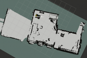
2D grid map