
Project Reports
- Conceptual Design Review (CoDR, December 2019)
- Critical Design Review (CDRR, May 2020)
- Final Report (December 2020)
Project Presentations
- Preliminary Design Presentation (PDR, March 2020)
- Spring Validation Demonstration Tests (SVD, April 2020)
- Critical Design Review Presentation (CDR, May 2020)
- System Development Review Presentation (SDR, October 2020)
- Standards and Regulations Presentation (S&R, December 2020)
Progress Reviews
- Progress review 1, presented by Rohan
- Progress review 2, presented by Sanil
- Progress review 3, presented by Poorva
- Progress review 4, presented by Uma
- Progress review 5, presented by Sachit
- Progress review 6, presented by Rohan
- Progress review 7, presented by Sanil
- Progress review 8, presented by Poorva
- Progress review 9, presented by Uma
- Progress review 10, presented by Sachit
- Progress review 11, dress rehearsal
Individual Lab Reports
- ILR-01: Poorva, Uma, Sachit, Sanil, Rohan
- ILR-02: Poorva, Uma, Sachit, Sanil, Rohan
- ILR-03: Poorva, Uma, Sachit, Sanil, Rohan
- ILR-04: Poorva, Uma, Sachit, Sanil, Rohan
- ILR-05: Poorva, Uma, Sachit, Sanil, Rohan
- ILR-06: Poorva, Uma, Sachit, Sanil, Rohan
- ILR-07: Poorva, Uma, Sachit, Sanil, Rohan
- ILR-08: Poorva, Uma, Sachit, Sanil, Rohan
- ILR-09: Poorva, Uma, Sachit, Sanil, Rohan
- ILR-10: Poorva, Uma, Sachit, Sanil, Rohan
Design Brainstorming
Check here
Software
Our code-base can be found on the team’s GitHub page.
Hardware
We are using PIXBOT, the world’s first open-source autonomous chassis, designed and developed by PIX Moving. The vehicle control code, CAD models and other design documentation are detailed on the Gitlab page here.
Sensor Datasheets
PCB Design
To mount a LIDAR and the NVIDIA Jetson on the RC car, our temporary testbed, we would need to build a power distribution system to efficiently power all required components.
Power Source
The source of Electrical power for our system is a series combination of two 11.1V LiPo battery. This is because our components require a maximum of 12V and connecting in series will ensure we supply the required voltages at all times. The specifications of the battery are as follows:
- Turnigy 1450mAh 3S 11.1v Transmitter Lipoly Pack
- Size: 93x40x14mm
- Charge Plug: JST-XH
- Discharge: Futaba JR
- The LiPo battery has a voltage range of 10.7 to 12.4V between charges and has a current output of 1.45 Amps
Powered Subsystems
- Nvidia Jetson TX1
It can take a maximum of 19V, 4A supply input. We are planning to supply a 12V/3A supply to the Jetson. Since our battery supply is equivalent to 22.2V, we would use the MIC29300-12WU voltage regulator. The peak current allowed for proper functioning of the Jetson is 4A, and we plan to operate within 3A. We will use 1 CGRID connector for supplying output to the Jetson. We will have a circuit for reverse voltage and over-current protection by including a diode and a fuse. - Lidar
We will also have a 12V/2A output for the VLP16 Velodyne LIDAR. Since the current requirements are different compared to the Jetson, we will use a separate Voltage regulator for the same. Again, a CGRID connector will be used at the output and protection will be given against reverse input, short circuit and over voltage. An LED indicator would be used to indicate whether or not this sensor is powered or not. We will also add a manual switch for the Lidar at the output so that power is not distributed unnecessarily.
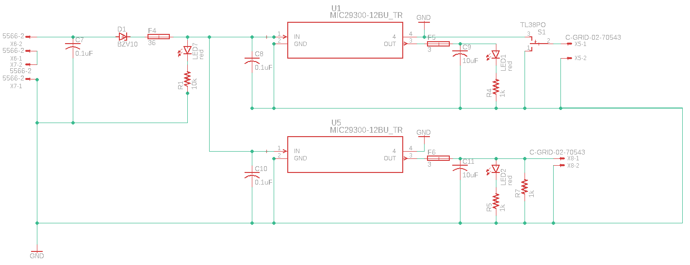
Figure 1: Power Distribution Board Schematic
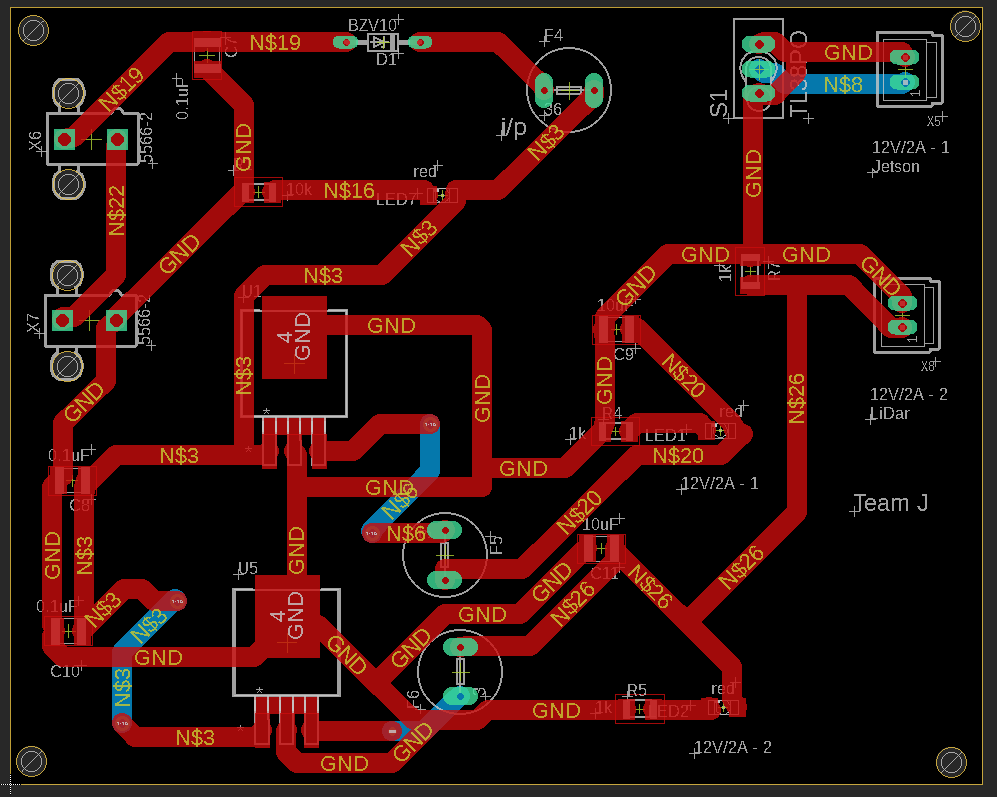
Figure 2: PCB Power Distribution System Layout
Datasheets:
Voltage regulator (high current family): MIC 29300
Voltage reference diode: BZV10
Software Flowcharts
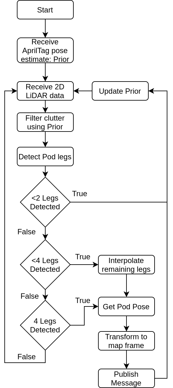
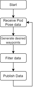
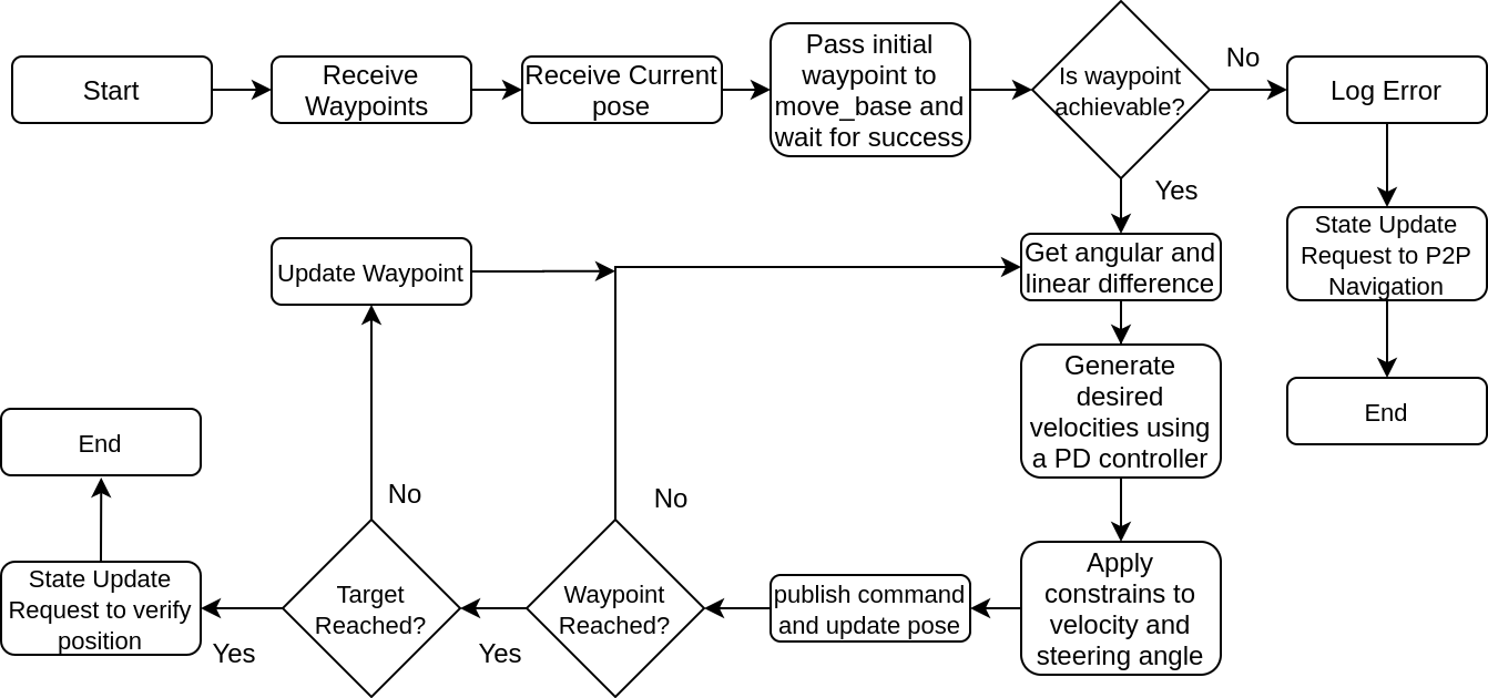
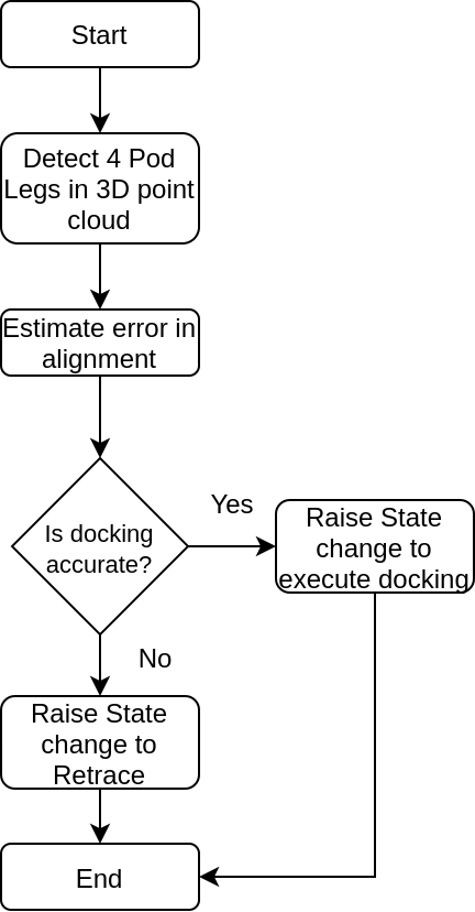
Pod Localization Waypoint Generation Approach Navigation Position Verification
Component Evaluation and Testing
Most of the hardware component evaluation and tests will be taken up in the fall semester. We did the following experiments and testings in simulation.
| Experiment | Procedure | Results |
| 1. Evaluate use of 3D LiDAR for docking verification position | Place the chassis under the pod at different orientation and test offset against ground truth | We found that the 3D point cloud at certain channels of VLP-16 can be used to detect pod legs and we can find the offset from the center. However, the accuracy was not consistent due to VLP-16 simulation having some bugs observing the same data over time. We also found that VLP-16 data under 1m has lower accuracy and is more prone to noise. We will evaluate this on hardware |
| 2. Evaluate 2D LiDAR for Pod leg detection | Place chassis in front of Pod in different orientations and estimate pod center | We were able to estimate the center of Pod with high accuracy even when we were viewing 2 or 3 legs, it was very robust. However, if the range exceeded the LiDAR beams were missing pod legs. We used this to define our PHZ length. |
| 3. Evaluate fiducial markers for Pod estimate | Place chassis in front of Pod in different orientations and place different markers on Pod, estimate position of markers. Change marker type and sizes | We tested ARTags and AprilTags and decided to use the latter due to easy interfacing. The size of AprilTag was decided to be 20cm to accurately detect and estimate pose at PHZ length |
| 4. Tune PD parameters for Pure Pursuit Navigation | Give waypoints to chassis and evaluate accuracy at final waypoint | We found that a damping term helped the chassis not to overshoot the target and tune parameters. We also found that we can add a potential field based constraints on velocity and steering angle based upon the Euclidean distance to the final waypoint to improve accuracy. It also made the system more reliable as in the chances of a collision near the final waypoint reduced. |
| 5. Find optimum Placement of sensors | Place sensors at various location and test their functionality and ease of accessibility
|
We observed that
|