
Schedule
Schedule for Spring Semester
Gantt Chart for Project Schedule
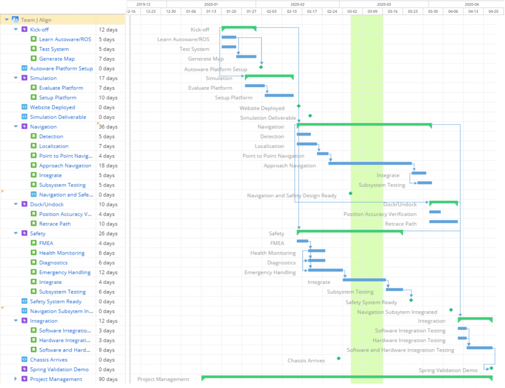
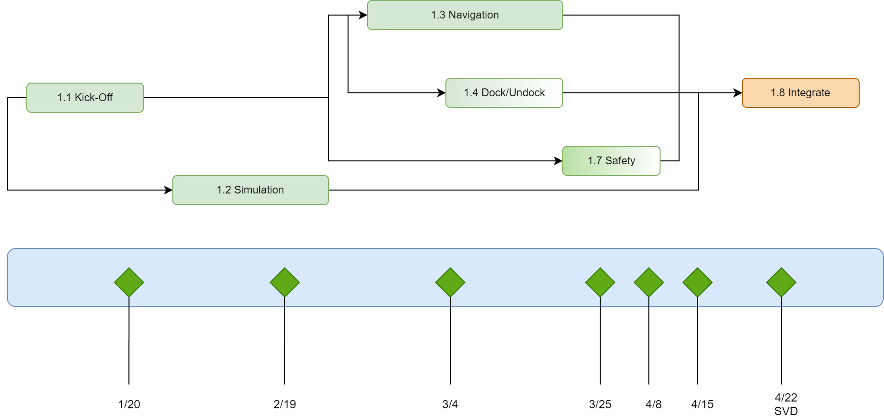
| Date | Milestones for Spring Semester |
| 1/20 | Autoware Environment Setup |
| 2/15 | Website Deployed |
| 2/19 | Simulation Platform Setup on CARLA-Autoware |
| 3/4 | Navigation subsystem design & Simulation setup for docking ready |
| 3/25 | Navigation subsystem components tested |
| 4/8 | 1. Navigation subsystem developed
2. Docking subsystem components tested in in Simulation 3. Safety subsystem components Object Detection and Behaviour Prediction developed |
| 4/15 | Health Monitoring Design Ready, Navigation Subsystem and Docking subsystem Software Integration done. |
| 4/22 | SVD |
Schedule for Fall Semester
Gantt Chart for Project Schedule
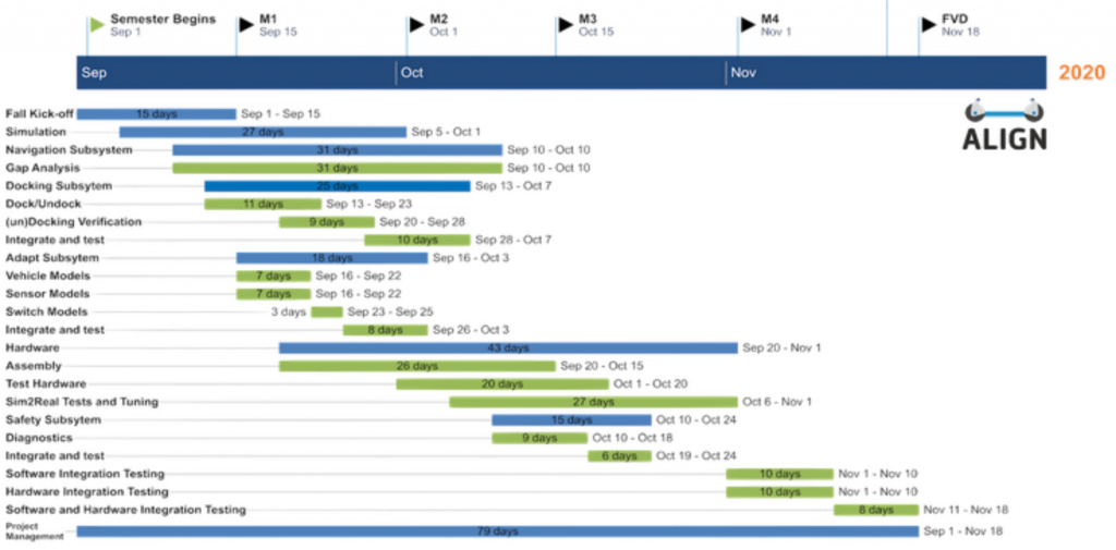
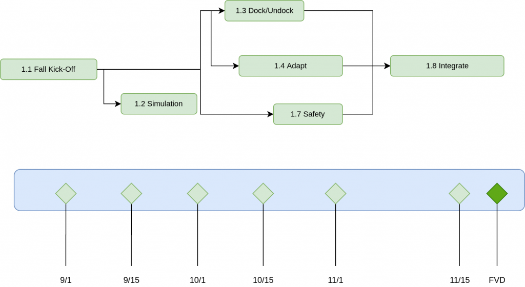
| Date | Fall Milestone |
| 9/1 | Gap Analysis, Navigation Subsystem |
| 9/16 | Docking subsystem designs completed |
| 09/30 | Vehicle models ready, Simulation merged |
| 10/14 | Docking system completed and tested in simulation.
sim2real test setup ready |
| 10/28 | Docking, Navigation and Safety Subsystem integrated in simulation, |
| 11/11 | All subsystems finished and unit tested, sim2real test setup ready |
| 11/18 | FVD |
Presentation Order for Progress Reviews:
For spring and fall semester: Rohan -> Sanil -> Poorva -> Uma -> Sachit
Test Plan
Detailed Experiment for the full system validation can be found here
Spring Validation Demonstration
Note: Tests will be performed in Simulation
Equipment: Laptop with Autoware and Gazebo, and a precomputed map of the Gazebo world.
|
Validation Experiment Description |
Procedure |
Validation Criteria |
The system will navigate from one end of the designated area in simulation to a distance of 2m from the payload handling zone entry point, without any obstacles in the way. |
|
|
The system will stop at a distance of more than 30 cm from the detected obstacle (dynamic and static). The minimum dimensions of said obstacles will be 30×30 cm 2 (height and width). System to demonstrate its safety behaviors if some node crashes. |
|
|
Once it has reached the payload handling zone, the system will plan a path for aligning with the payload handling zone and execute it. The system will verify the accuracy of the docking (and relay the output to the user). Done in Gazebo Simulation. |
|
|
We will introduce a slight misalignment between the pod and chassis manually and check if the system detects this and re-performs the docking alignment process. |
|
|
Fall Validation Demonstration
Objective: To validate the subsystems and meet mandatory performance requirements
Location and Conditions: NSH Basement (B level) and Simulation World
Equipment: Sensor jig, a pod with fiducial markers, laptop with Autoware and dependencies, and a precomputed map of the testing environment
Procedure
Simulation
- Launch the simulation, place the chassis in the pre-mapped environment, and instruct it to go to a pod location to demonstrate point-to-point navigation.
- Place an obstacle in the planned path. Verify that the Health Monitoring System (HMS) transmits an error message to the system and the chassis stops as a result. Remove the obstacle and verify that the chassis continues on its planned path.
- After the chassis reaches the Payload Handling Zone (PHZ), verify that the PHZ and pod are identified.
- Verify that the docking command has been issued by the state machine.
- Issue a command to the chassis to transport the pod to the drop-off location and then undock with it.
- Sensor nodes will be crashed to observe system behavior.
- Repeat the Approach Navigation step multiple times. For one trial introduce misalignment after the chassis achieves docking position to demonstrate retracing.
- Monitor the system states and logs during the whole process.
Hardware
- Test 1: Setup the hardware jig and make a pedestrian walk in front of it. Demonstrate pedestrian detection and trajectory prediction and compare to ground-truth positions.
- Test 2: Place the jig in front of the pod and demonstrate relative localization by localizing the pod and comparing it against ground truth values. Demonstrate the docking verification check by placing the jig under the pod and comparing the predicted docking pose error with the actual (ground-truth) pose error.
Validation Criteria
- Simulation: The chassis will plan a path to the desired pod, identify it, and dock with it. It will then drop the pod off at a predefined undocking location. State transitions happen only when the last action has been completed. The logs will show the system health, states, and results in an easily readable format. The metrics that will be met are:
- Docking will be done within 120s. (M.P.2).
- The simulation should be successful 85% of the time. The success criterion subsumes M.P.1 (chassis will identify pod when it is within 2m of the PHZ), M.P.3 (chassis will achieve docking pose with an error margin of ±5 cm in position and ±5.54 degrees in orientation), and M.P.8 (chassis will identify PHZ 90% of the time).
- Hardware: Validate algorithms with real-world data and show that the same accuracy criteria are met. The metrics that will be met are:
- Test 1: Object locations are detected with an accuracy of ± 5 cm (M.P.6).
- Test 2: Predicted pod position (x,y) for relative localization is within 20 cm of the ground-truth, and the orientation (yaw) is within ±11.80 degrees of the ground-truth. The same margins hold for the predicted docking pose (x,y, yaw) error and actual error.
Updated Risks
| Risk ID | Risk | Requirement | Type | L | C | Mitigation |
| R1 | Issues with legacy system | All MPs | Technical
Schedule |
5 | 5 | – Develop plan to test chassis
– Continue developing and testing algorithms in simulation |
| R2 | Unable to assemble chassis | All MPs | Technical
Cost Schedule Programmatic |
5 | 5 | – Develop plan to assemble chassis
– Test subsystems in simulation – Move FVD to simulation |
| R3 | Sensors stop working | MPs 2, 3, 4, 7, 8, 9 | Technical
Cost |
2 | 3 | – Formulate sensor test plans and safeguarding procedures
– Use hardware abstraction layer |
| R4 | Testing infeasible due to weather conditions | All MPs | Technical
Schedule |
3 | 3 | – Test subsystems in NSH B-level |
| R5 | Communication gap with sponsor | All MPs | Schedule | 4 | 4 | – Document work
– Provide regular updates |
| R6 | Issues in Subsystem Integration | MPs 5, 6, 8 | Technical
Schedule |
4 | 4 | – Perform testing on individual subsystems
– Develop integration test plan initially |
| R7 | Overambitious requirements | MPs 2, 3, 4 | Technical
Schedule |
3 | 3 | – Refine requirements and descope system if necessary |
| R8 | Integration issues
with code |
All MPs | Technical
Schedule |
2 | 3 | – Document work with changes implemented
– Perform unit testing at each level possible – Use a common framework to develop code |
| R9 | Global pandemic occurs, causing campus shutdown | All MPs | Programmatic | 1 | 3 | – Continue working simulation
– Follow government and university guidelines regarding health and working conditions – Develop schedules and have regular follow ups with team members |
| R10 | Algorithms do not pan out in real-life | All MPs | Technical Schedule | 3 | 4 | – Test subsystems individually to assess if problem lies in software or is actually due to conversion from sim2real |
Parts List
Can be Found here
Issues Log
Can be found here