
System Requirements
Mandatory Performance Requirements
The system will:
- MP1. identify that it is in the proximity of the payload handling zone (PHZ) when the chassis is within 2m of the entry point of the PHZ.
- MP2. complete docking in less than 120 s. This includes docking initiation, verification, and retries.
- MP3. achieve docking pose with a maximum error of ±5 cm in final position and ±5.54 degrees in its final orientation.
- MP4. update sensor & vehicle models with a maximum latency of 60 s.
- MP5. diagnose failures within 2000 ms from the occurrence.
- MP6. detect object location with an accuracy of ±5 cm.
- MP7. maintain a minimum distance of 30 cm from obstacles.
- MP8. be able to identify the pod upon reaching PHZ 90% of the time.
Mandatory Non-functional Requirements
The non-functional requirements represent 3 categories of requirements. M.N.1 to M.N.7 are sponsor-imposed constraints. M.N.8 and M.N.9 will help us maintain the integrity of our work. M.N.10 and M.N.11 will help us in ensuring the safety of our system and its surroundings.
The system will:
- MN1. use Autoware as the framework for the software stack.
- MN2. operate in a geofenced environment.
- MN3. operate in a well-lit environment.
- MN4. operate on asphalt.
- MN5. be powered by an on-board battery.
- MN6. communicate wirelessly in the ISM band.
- MN7. be maintainable: code should be modular and well documented.
- MN8. be unit-testable.
- MN9. be reliable: subsystem failure modes should be well-defined and detectable.
- MN10. be compliant with relevant standards and regulations.
Desirable Performance Requirements
The system will:
- DP1. complete docking in less than 60 s. This includes docking initiation, verification, and retries.
- DP2. achieve docking position with a maximum error of ±2.5 cm in final position and ±2.77 degrees in its final orientation.
- DP3. diagnose failures within 1000 ms from the occurrence.
Desirable Non-functional Requirements
The system will:
- DN1. operate in low-light conditions.
- DN2. be serviceable: sensors should be easily accessible for servicing.
- DN3. be scalable: behaviors should be transferable to wider uses with minimal changes.
- DN4. be extensible: additional features and upgrades can be added to the system while maintaining backward compatibility.
- DN5. be recoverable: the system should be able to recover from any error state (even if human intervention is required).
- DN6. always have a state of charge of the chassis battery greater than 30%.
- DN7. provide visual and auditory alerts.
Functional Architecture
Cyber-physical Architecture
High-level System Overview

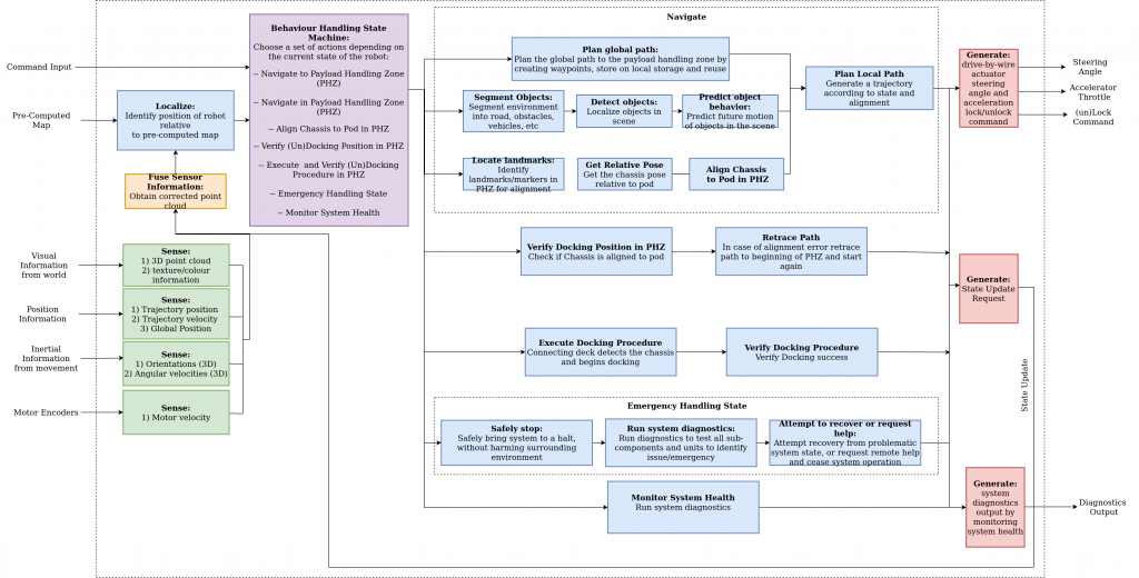
The inputs to the system provide it with the necessary information and energy that is required for its proper functioning. This information is processed and necessary operations are performed to generate control commands – steering, throttle, and docking – to drive the system as desired. Feedback information is also generated to monitor the health of the system and update the state to modify system behavior accordingly.
The subsystems that work in coordination within the system are:
- Sensing
- Navigation
- Docking
- Safety
The sensing subsystem provides the necessary information that is required to perceive the environment. Visual information from a camera is used to generate a 3D point cloud, along with texture and color information. Position, velocity and orientation information is obtained from position, inertial sensors and motor encoders for localization. A docking sensor is used to identify whether or not the pod and chassis are aligned for locking/unlocking.
The information from this subsystem, along with the pre-computed map is processed and provided to the state machine, which determines the behavior of the system depending on the processed input. The major possible states for the system include docking, navigation, and safety. The system will navigate from point A to point B, near the payload handing zone (PHZ). It will then plan an approach in the PHZ to successfully dock/undock with the payload. Upon reaching the docking position it will verify its position to see if the system can proceed with the physical act of locking/unlocking and pull a state update request accordingly. In the docking state, after verification, the pod physically locks/unlocks and verifies locking/unlocking. In case of an emergency, the system safely stops, runs system diagnostics, and attempts to recover or request for help. The heartbeat of the system is also continuously monitored and necessary actions are taken in case of any discrepancy.
Subsystem Descriptions
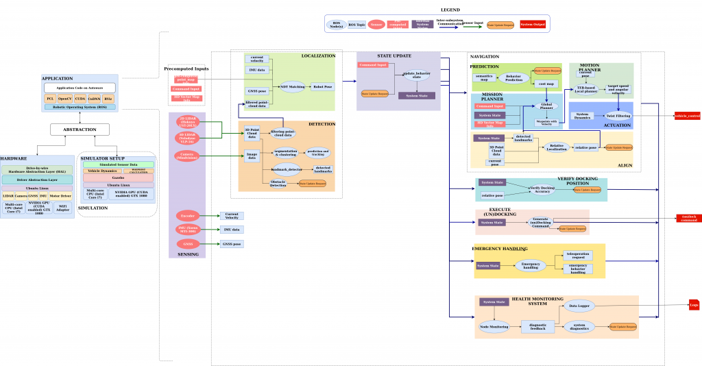
The cyberphysical architecture can be broadly divided into 4 subsystems: Sensing, Navigation, Docking, and Safety.
Sensing
The sensing stack consists of a 3D LiDAR (VLP-16), a 2D LiDAR (Hokuyo UST 20LX), and an RGB camera (Mindvision)
The 3D LiDAR is used for the localization of the chassis and the pod. It is also used to estimate the error in the docking position and localizing obstacles. The 2D LiDAR is used for relative localization of the pod with respect to the chassis, docking pose verification, and also detecting obstacles and their distance from the chassis. The RGB camera is used by the detection subsystem for identifying AprilTags on pods and objects (potential obstacles) that are commonly observed in campus environments. The RGB camera is used by the detection subsystem for identifying AprilTags on pods and objects (potential obstacles) that are commonly observed in campus environments.
Navigation
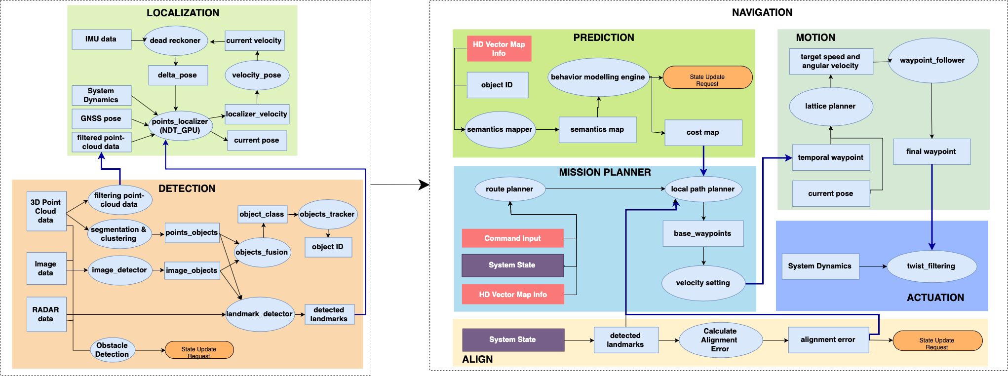
Sensing and Navigation Subsystems
This block is responsible for localizing the system in the environment. This subsystem is entered when the state changes when the move command is issued. Motion is generated until the final destination is reached. The navigation block exhibits two behaviors: point-to-point navigation which involves basic go-to-goal and obstacle avoidance behavior, and approach navigation which involves careful planning and executing motion towards the goal location in PHZ. The navigation subsystem comprises several blocks which are discussed below.
Detection: This block processes perception sensor data to detect landmarks, objects, and obstacles. Object IDs are created, the system state is updated if a desirable (like the payload handling zone or docking markers) or undesirable (like an obstacle) landmark is detected, and the detected landmarks are fed as input to the localization block.
Localization: Our system localizes itself by using the Normal Distributions Transform (NDT) Matching node of Autoware given an estimate of its initial pose in the map frame. NDT Matching node uses the 3D LiDAR point clouds and publishes the estimate of the current pose.
Prediction: The prediction block is responsible for keeping track of object positions over time and predicting their position at the next instant in time. It does by a 2nd order polynomial curve fitting using the positions obtained from the sensing subsystem.
Motion Planning and Mission Planner: We use a custom free space global planner that switches between Dubins curves and Reed-Shepps curves and teb_local_planner from ROS move_base to execute that path. This allows the chassis to navigate freely in the geofenced environment. The approach navigation is done in steps of four waypoints. The steering angle and velocity limits depend on how close the chassis is to the Pod. The first two waypoints are followed using the same planner as above. This allows us to perform advanced maneuvers such as reversing and turning. The two remaining waypoints are executed using a pure pursuit controller with a PD controller. This allows the chassis to approach the target in a more controlled manner. With the GUI, the user can also directly instruct the chassis to perform approach navigation.
Align: The Align block is responsible for the estimation of pod pose for approach navigation in the PHZ. This block performs relative localization to estimate the pose of the pod using the 2D LiDAR and AprilTag data and is fed as input to the planning block for executing highly calibrated motion. To localize the pod, we fuse multiple sensor modalities to obtain an accurate estimate of the center of the pod. We obtain a rough estimate using the detected AprilTags. After obtaining this rough estimate, we remove clutter surrounding a particular radius from the rough center estimate. We then refine the estimate using lidar measurements. After detection and estimation, we begin the docking maneuver. Thus, this subsystem is activated in the approach navigation state once the PHZ is reached. This block also triggers the Verify Docking Position function of the Docking subsystem once the chassis finishes Approach Navigation.
Docking/Undocking
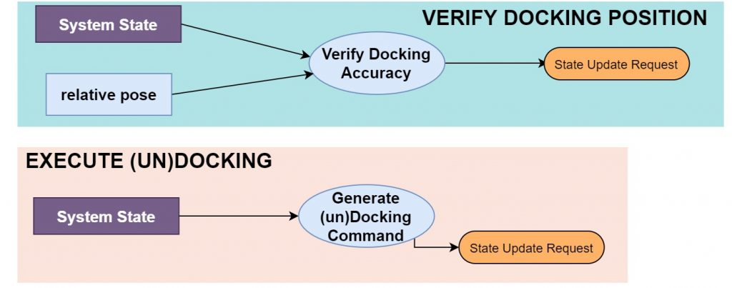
The docking subsystem is responsible for the physical act of docking/undocking and system adaptation to new payloads. We estimated cylindrical thresholded regions (white regions of Figure 24) around each leg. We verified Docking Pose by estimating the pose of the center of the chassis using this 3D LiDAR data. If the error in position and orientation is less than 5 cm and 5.54 degrees respectively, the system proceeds with the docking/undocking, otherwise, it retraces its path to the beginning of the PHZ.
Safety
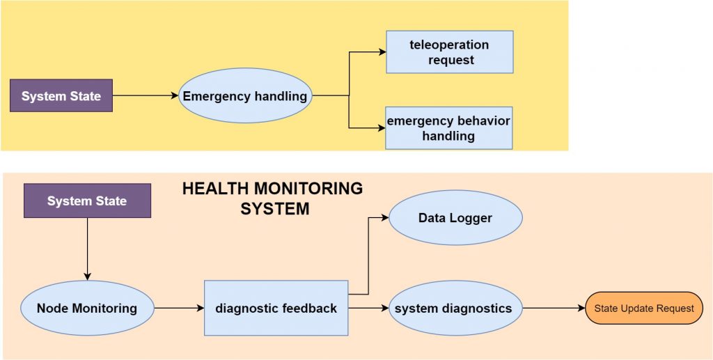
This subsystem ensures the safe and reliable operation of the chassis. This again is a block that is always operational irrespective of the system state. It is divided into two blocks:
Health Monitoring System: This block monitors the functioning and outputs of the critical nodes using a heartbeat, i.e. periodic back and forth flow of data. This allows for the detection of crashes and failures, or if the node outputs are exceeding thresholds. The heartbeat is also used to provide diagnostic feedback and diagnose failures. If any failures are detected the system state is updated to the emergency handling state.
Emergency Handling: Whenever an unexpected behavior is encountered the system enters the emergency state. For example, when an obstacle is detected in the path, the emergency is pressed, a critical node crashes, sensors stop functioning or a user issues an emergency signal, this state is entered. The first response is to safely halt the system’s motion, which is followed by logging the reason for the same. If needed a teleoperation request is raised for manual intervention.