System Requirements
| ID | Name | Class | Type | Description |
|---|---|---|---|---|
| R03 | Produce Worksite Maps | Functional | Technical | The system shall output maps of the worksite |
| R04 | Traverse Worksite Terrain | Functional | Technical | The system shall traverse worksite terrain |
| R05 | Autonomous Operation | Functional | Operation | The system shall operate autonomously after receiving operator/mission commands |
| R06 | Level Craters | Functional | Technical | The system shall level individual worksite crater surfaces |
| R07 | Smooth Craters | Functional | Technical | The system shall smooth individual worksite crater surfaces |
| R08 | Level Worksite | Functional | Technical | The system shall level entire structured worksite |
| R09 | Smooth Worksite | Functional | Technical | The system shall smooth entire structured worksite |
| R10 | Grading Throughput | Non-Functional | Technical | The system will maintain sufficient throughput (quantification tbd) |
| R11 | Sufficient Energy | Non-Functional | Technical | The system will have sufficient energy to complete entire worksite task without intervention |
| R12 | Safety Features | Non-Functional | Technical | The system will possess safety features to reasonably minimize human hazard |
| R13 | Operator Monitoring | Non-Functional | Operation | The system will produce real time monitoring and visualization for the operator |
| R14 | Technology Extensibility | Non-Functional | Programmatic | The system will be documented and prepared such that it can be handed off easily to future responsible party |
| *R15 | Environmental Robustness | Stretch | Technical | The system should be robust to expected environmental requirements |
| *R16 | Stress Test | Stretch | Technical | The system should be tested against increasingly difficult terrain |
| *R17 | Unstructured Terrain | Stretch | Technical | The system should be capable of leveling unstructured terrain |
| *R18 | Remote Teleop | Stretch | Operation | The system should be capable of teleoperation through a video feed |
| *R19 | Weight | Stretch | Technical | The system should be as light as possible to mimic lunar capability |
| *R20 | Cost | Stretch | Budget | The system should cost less than $5000 USD |
| *R21 | Portability | Stretch | Operation | The system should be portable on short term basis |
| *R22 | User hazards | Stretch | Operation | The system should not pose hazards to surrounding people |
Performance Requirements
| ID | Name | Class | Type | Description |
|---|---|---|---|---|
| R03-1 | Produce Worksite Maps | Performance | Technical | The system will output ≥1 human interpretable data product of worksite topography map pre and post grading |
| R04-1 | Traverse Worksite Terrain | Performance | Technical | The system will traverse worksite terrain up to ≤ 15 deg |
| R05-1 | Autonomous Operation | Performance | Operation | The system will operate autonomously after receiving operator/mission commands with 0 unplanned interventions |
| R08-1 | Level Worksite | Performance | Technical | The system will start and finish its operation in a worksite with a ≤ 1 deg total fit plane grade as measured against the gravity vector |
| R08-2 | Worksite Minimum Diameter | Performance | Operational | The system will operate within a worksite of ≥6m diameter |
| R08-3 | Worksite Environment | Performance | Operational | The system will operate continuously in uncontrolled ambient lab environment, atop Quickcrete Playsand 1113 w. sand blend impurities |
| R09-1 | Worksite Smoothness | Performance | Technical | The system will smooth the entire worksite to ± 3cm max deviation from fit plane with standard deviation ≤ 1 cm. |
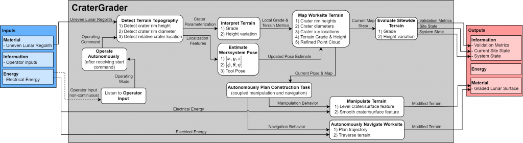
Functional Architecture
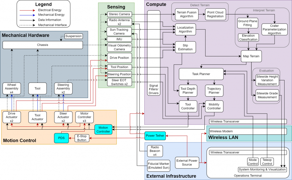
Cyberphysical Architecture
CraterGrader Rover

The CraterGrader worksystem is composed of a capable, 4-wheel drive mobility platform, with a body-averaging suspension and double-ackerman steering. It contains an advanced suite of sensors for worksite perception, localization in GPS-denied environments and slip estimation. All required compute for autonomous operation occurs onboard the worksystem in the form of a Jetson Xavier. Additionally, there is a midbody tool platform on the underbelly of the platform for earthmoving, where tool configurations can be tested. The rear of the vehicle has an interface for smoothing tools currently in development.
Rover Subsystem
The rover subsystem shown in Figure 1 contains all the power electronics, motion control, mechanical hardware, and mechanisms of the rover including the blade tool.

Figure 1: Rover Subsystem Components
AutoCrawler is equipped with a 4-wheel drive, double-ackerman, body-averaging suspension which will help with the overall efficacy of the system and will allow for a smooth platform for mounted sensors. The onboard vehicle electronics will be housed in the square tube chassis displayed. The wheels are powered by a pair of high-geared brushed motors with encoder feedback, driven by RoboClaw 15A motor controllers. The blade tool is implemented using a similar setup. The blade shown in the diagram is only shown for illustrative purposes and does not represent a final design. The current blade is driven from a linear carriage actuator, and allows for various angles of deployment. Future additional tool configurations are being currently evaluated. Initially other platforms were considered, such as the tracked vehicle Icebreaker, but the size factor and maneuverability afforded by the dual-ackerman steering of the AutoCrawler eventually won out.
Sensing Subsystem
The sensing subsystem as shown in Figure 2 encapsulates all sensing and feedback on the worksystem. This includes low-level sensors such as the actuator encoders and high-level sensors such as the mounted Realsense 435i. The subsystem also includes necessary elements of sensing including filtering, calibration, mounting, and unit testing. In the current configuration, a Realsense mounted on a sensing mast has been incorporated for mapping of craters and topography and a downward-facing fisheye camera acts as the visual odometry sensor. The onboard IMU obtains inertial measurements fused in software with absolute position from the external Ultra-wideband Beacon configuration. Initially, strong consideration was given to using LiDAR, but the long range benefits of lidar was determined to not be required for the worksite size.

Figure 2: Sensors Subsystem Depiction
Compute Subsystem
The compute subsystem encompasses computing hardware onboard the vehicle, along with drivers and enclosures. An onboard computing approach has been implemented, using a NVIDIA Jetson Xavier. The compute subsystem includes drivers for peripherals that contact the compute board, such as motor controllers and sensors (seen integrated in Figure 3). Initially a distributed compute method was considered, where low latency processes would run independently from high-cost computations, but this method was determined to be overly complicated for the project timeline without providing enough of a known benefit.

Figure 3: Integrated On-board Compute Subsystem
Software Subsystem
The software subsystem comprises the algorithms for terrain detection, localization, mapping, slip estimation, planning, control, and final site evaluation. All components of the software subsystem are implemented using ROS2 framework, an open-source middleware enabling publisher/subscriber capabilities. Middleware fallbacks included core Flight System or F’ (F Prime), both having been developed by NASA for flight software. However these were not chosen due to the team’s familiarity with ROS2 as well as the ability to leverage existing packages within the ROS2 ecosystem. A subset of the cyber-physical diagram, focusing on the compute and software subsystem, can be seen in Figure 4.
The software pipeline is detailed below; algorithm fallbacks will be determined at later stages as they are further developed. As a preprocessing step, any raw data received from the sensing subsystem is passed through appropriate signal filters, outputting denoised readings to be interpreted by subsequent algorithms in the software pipeline. The terrain detection algorithm takes the most recent point cloud and RGB image as input from the stereo camera. The terrain fusion algorithm combines both sources of information allowing learning-based segmentation of relevant features (terrain and craters) within the environment. The result is a labeled point cloud that is merged with previous measurements through point cloud registration to iteratively build a terrain representation. Variations in terrain are measured by fitting a ground plane to the point cloud. Points off the plane, determined by a threshold, are classified as areas that need to be graded or filled. Individual craters are also identified during this step, parametrized by their rim diameter and height.
The localization algorithm takes global measurements from the radio antennae and sun-tracking camera to estimate pose, as well as slip estimation information which embeds odometry data from the IMU, visual odometry camera, and hall effect sensors. This will provide all the necessary information to generate a pose estimate from traditional localization algorithms, such as Kalman Filter variants or Graph-based Simultaneous Localization and Mapping. This pose estimate, in addition to the point cloud representation of the terrain, is fed into the mapping algorithm, which synthesizes an accurate representation of the worksite and the worksystem’s pose inside of it. The mapping algorithm is additionally responsible for maintaining the map as the environment changes, for example when craters are filled during operations.
The task planner uses the map and robot pose to generate high-level behaviors for the robot to accomplish. Such behaviors may include targeting a particular crater to fill or focusing on sitewide grading. These behaviors would plan tasks considering coupled navigation and tool manipulation, before passing the plans to lower level planners and controllers. In the navigation context, the task planner would determine an appropriate goal pose for the robot, such as a target pose to navigate towards a crater. The trajectory planner will then generate a time sequence of waypoints that define an idealized reference trajectory for the vehicle to follow, and the mobility controller will determine the appropriate steering and drive commands to follow this trajectory as best as possible, based on actuator feedback. In the tool manipulation context, the task planner would compute a desired longitudinal slip, determined as a function of the quantity of sand that needs to be moved to achieve the current grading behavior. The tool planner uses the desired slip and estimated actual slip to compute a reference tool position, and the tool controller leverages actuator feedback on the tool to close the loop on tool position.
Sitewide evaluation employs a similar approach used in the terrain measurement algorithm to compute performance metrics; a ground plane is fit to the sitewide map to quantify variations in terrain height and grade. These metrics are reported to the operations terminal for continuous feedback on the robot’s performance, and are also used by the robot to determine its termination condition. The robot will decide that it has completed sitewide grading when: (a) measured sitewide height and grade are within pre-specified thresholds, and (b) the robot has determined that it has gathered measurements of the entire worksite.

Figure 4: Software Subset of Cyberphysical Diagram
External Infrastructure Subsystem
The external infrastructure subsystem visualized in Figure 5 is a combination of the items necessary to operate the worksystem that are not aboard the vehicle including the operations terminal, fiducial markers as a pseudo-sun, and the Ultra-wideband beacons. This subsystem also includes the independent evaluation tools used to measure the site after grading such as a tripod-mounted FARO scanner. A backup for the multiple AprilTags around the perimeter of the worksite was considered, but the FARO scanner has proved to be relatively simple to setup and can provide a robust ground truth.

Figure 5: External Infrastructure Supporting Work system
Test Subsystem
The Integration and Test subsystem include the reports required to operate a test and the testbed/test site itself, as well as the physical test site, and integration documentation and work. The selected nominal development test site is the prebuilt GHC sandbox in GHC. Original alternatives included outdoor test sites nearby in Pittsburgh, however the convenience of the GHC sandbox as well as the recent expansion (Figure 6) has meant that there is no need for an alternative.

Figure 6: Gates Hillman Complex Sandbox