Perception Subsystem
Pose Estimation
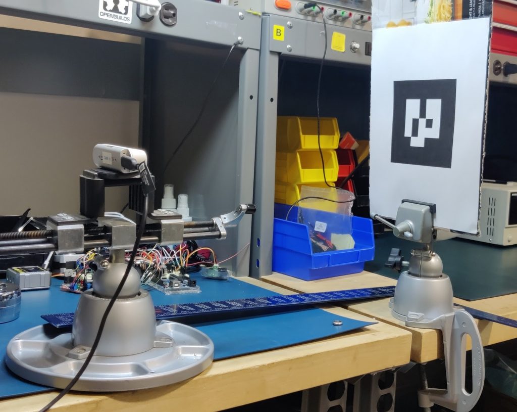
AR markers were used as fiducial markers for pose estimation since they had better ROS support and allowed us to estimate the pose of the tag in 3D space using information from the RGB image as well as the depth image. Analysis and unit testing of pose estimation was performed by setting up a large fiducial marker on a vice at a known distance from the camera frame, and oriented at a right angle along one axis as shown in figure 1. The pose estimation ROS Node was executed for 10 image frames and the mean of the estimates was taken to verify against our performance requirements.

Fig 1. Unit testing setup of the pose estimation framework
Evaluation Metric: According to M.P.R.1 and M.P.R.2, the container pose estimation algorithm should detect position with an error of < 10 mm and container orientation with an error of < 5°.
Achieved metric: Our system detects container pose with an error of < 5 mm and container orientation with an error of < 2°.

Fig 2. Evaluation of the average position and orientation error over 10 attempts
Ingredient Validation
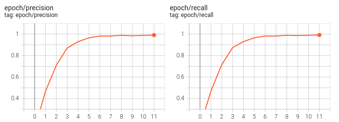
Unit testing of this ingredient validation was majorly performed by verifying the validation metrics while training the model, and verifying that the ROS Service correctly generates the expected prediction during inference while in operation.
Evaluation Metric: According to M.P.R.3, the system will validate ingredients stored in a fixed set of translucent containers with a precision of over 85% and recall of over 90%.
Achieved metric: Our system validates ingredients stored in a fixed set of translucent containers with a precision of over 99% and recall of over 99%.

Fig 3. Validation Precision & Recall over each training epoch
Container Weight Estimation using Force-Torque Sensor
We used the UR5e pendant’s software calibration sets to perform the initial calibration. We obtained the tool center point, orientation, pose, center of gravity after the calibration was performed. This calibration was done to prevent false protective stops.
We obtained the joint torque along X, Y, Z axes directly from the values published to ROS topics by the UR5e driver. We isolated the torque values along X axis and used the mass-torque relationship to compute the container weight;
Torque = m x g x L
Where,
m: mass of the container
g: Acceleration due to gravity
L: Length of the moment arm (distance from the wrist joint to center of mass of the container)
The weight of the container obtained using this method gives us a weight estimate within +-50 grams of the actual container weight.
Controls Subsystem
The controller being used for dispensing was evaluated by running multiple trials requesting the system to dispense different quantities of ingredients within the typical request range of the ingredient. The evaluations were done with the containers being at different fill levels for each trial. The metric used for evaluation was the number of times that the dispensing process was out of tolerance. The evaluation results are shown in the graphs below. The green circles indicate trials that were within tolerance and the red circles indicate trials that were out of tolerance.


Overall System
Spillage
- Evaluation Metric: According to M.P.R.6, the system ensure ingredient spillage to be less than 5% by weight
- Achieved metric: Our system ensures ingredient spillage to be less than 1% by weight
Cycle Time
- Evaluation Metric: According to M.P.R.7, the system will dispense any ingredient in under 3 minutes
- Achieved metric: Our system dispenses any ingredient in under 2 minutes
Payload
- Evaluation Metric: According to M.P.R.8, the system will handle containers weighing up to 1.5 Kgs
- Achieved metric: Our system can handle containers weighing up to 1.5 Kgs
