Mechanical Subsystem
The mechanical subsystem includes the physical components that compose the UR5e robot and its environment. One of the major components of this sub-system includes the design and fabrication of the gripper fingers. The current finger design was arrived at after numerous iterations. The aluminum version of the gripper finger currently in use is shown in figure 2.
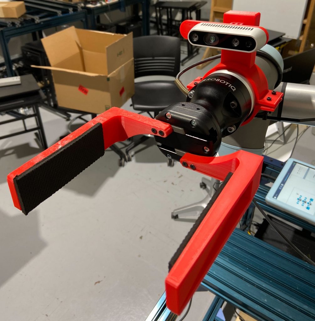
Fig 1. Final 3D printed gripper and camera mount

Fig 2. Aluminum gripper
Another major item that was manufactured was the camera mount (shown in figure 3).
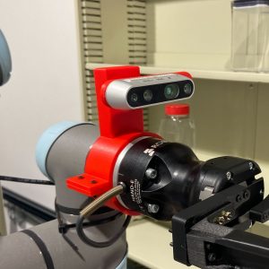
Fig 3. Camera Mount
In addition to the gripper manufacturing, we also build 3 stations.
1. Sensing station: This consists of a weighing scale and a spectral camera and is used for inventory update pipeline. The station is used to sense data and store an inventory of information about all ingredients prior to the cooking process.
2. Cooking pot 1 station: This station holds a cooking pot on top of a weighing scale. The cooking pot does not have a heating and a stirring element
3. Cooking pot 2 station: Cooking pot 2 is placed on top of another weighing scale and is securely mounted onto a sturdy wooden desk. This cooking pot has heating and stirring functionality.

Fig 5. Environment Setup with two cooking stations
Perception subsystem
The perception subsystem includes two major components so far:
Pose estimation
The robot picks up a container based on the 6-DOF pose estimated by the perception pipeline. We use AR Fiducial markers on the containers, and their pose is estimated with respect to the camera base link using the Perspective-n-point and the plane fit methods. This pose is then used to generate a pre-grasp position in front of the container to facilitate the next step of the perception pipeline.
In order to transfer the AR-tag pose from the frame of the camera to the robot’s base frame, the hand-eye calibration process has to be carried out as a precursory step. Hand-eye calibration was carried out using packages available in MoveIt.
The 3D data from the camera point cloud was also used to improve the stability of the pose estimates using the plane-fit algorithm.
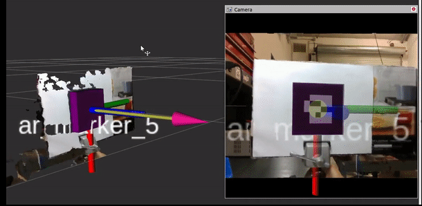
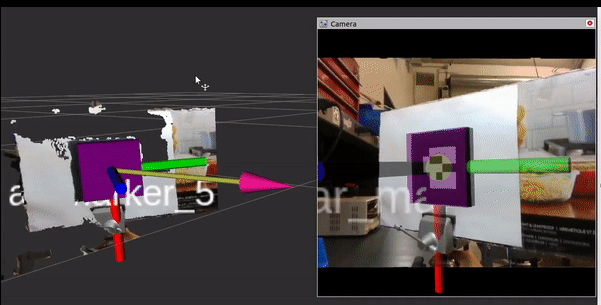
Fig 5. Pose detection using AR tags
Ingredient Validation
When the inventory update is being performed, the system needs to identify what ingredient is placed at each position and store it in the config file. Ingredient validation is done using two sensory modalities: RGB Image and Spectral data of the ingredient. The pipeline is as follows:

Fig 6. Flowchart of the ingredient validation pipeline
The pipeline starts out by capturing an RGB Image of the container from the pre-grasp position. If the ingredient can be classified into a category with a high confidence score, it is stored in the inventory. If not, or if the ingredient has been classified as one of the ingredients belonging to the visually similar category, then a spectral reading is captured during the inventory update step. A final classification is result obtained once the ingredient validation is performed using spectral data, and is stored in the inventory.
RGB Image Classification pipeline
This pipeline uses the EfficientNet-B0 model pre-trained on the Imagenet dataset. This was retrained on a dataset of ~20 ingredients containing about 150 images per class. Automated data collection and auto-labeling scripts were written to ease the addition of new ingredients to the dataset.

Fig 7. Automated data collection: The selected object will be tracked in subsequent frames and images are captured continuously.
The fine-tuned model was then adapted into a ROS service to ensure runtime efficiency during the functioning of the system, and to generate this prediction only when necessary.
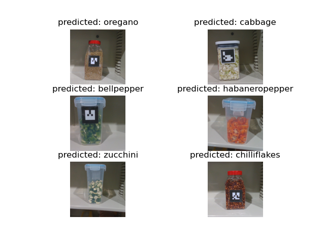
Fig 8. Predictions by the ingredient classification model
Spectral classification pipeline
We use the diffuse reflectance spectral camera from Allied Scientific Pro. The spectral camera only comes with a Windows SDK, therefore, we have an additional windows PC in our system that runs the sensor’s SDK and shares the spectral scans to the main Ratatouille PC.
Fig 9. NIRVascan Spectral camera
For classification, we collect a dataset about 20 spectral readings for each ingredient. One spectral reading comprises of the reflectance measurement of the ingredient across wavelengths from 900-1700 nm, hence it is a curve. For each new reading, the average Frechet distance is computed from the test sample to all the 20 samples of each ingredient in the dataset. The ingredient to which the average distance is minimum is classified as the category of the ingredient.
Fig 10. Spectral classification
Planning Subsystem
The planning subsystem involves two major classes of activities – task planning and motion planning. The task planning includes the portion of the state machine that determines the sequence of operations to be performed for each ingredient. The operations involved will also vary based on the results of the various condition checks involved in the process flow. For example, ingredient validation through the spectral camera might be necessary only if the visual information is insufficient to classify the ingredient with the necessary confidence.
The system has two major high-level tasks – inventory update and dispensing. We have two separate task planners in place for the two tasks, both implemented as a simple state machine. We accurately capture the pose of each container on the shelf during the inventory update flow to generate the system inventory which contains details of the presence, position, contents, and quantity of ingredient containers on the shelving unit. Once the unknowns in the system are corrected and recorded during the inventory update step, there is no need for localization of marker and marker-guided grasping motions during dispensing anymore. We simply move the arm directly to the saved location of each container as recorded in the inventory file and pick up the container. We also no longer need to validate the ingredient as we already have performed this ingredient identification during the inventory update step. This makes the dispensing process far simpler.
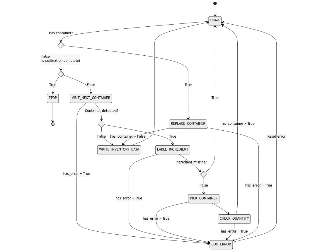
Fig 11. State Diagram for Inventory Update task planning
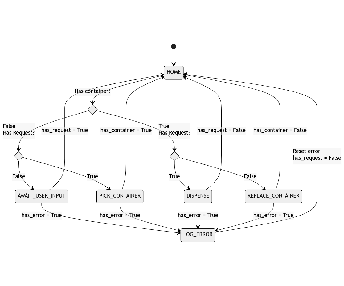
Fig 12. State Diagram for Dispensing task planning
While the task planner determines the movements that the robot is required to make, the motion planner determines the path that the robot shall use to reach the goal location. ROS MoveIt package has been used to manage the overall motion planning framework. Note that since a lot of the movements that the robot shall make will be repetitive, for most cases, predetermined waypoints shall be used. The environment that the robot operates in will be static in an ideal case, and moreover, the robot does not have any sensing capabilities to monitor the changes in its environment. Hence, no actual planning is required. On MoveIt, we use the PILZ Industrial Motion Planner, which is essentially a trajectory generator. Consequently, the planner can generate motion paths that are fast and deterministic (as shown in figure 7.). While the planner does not check for collision constraints during the trajectory generation, it ensures that the generated trajectory is collision-free. If the trajectory is in collision, an error is raised. This behavior is not detrimental as in a healthy operating state, the generated trajectories will not be in collision.

Fig 13. Joint velocity profiles in PILZ industrial motion planner
Controls Subsystem
The system uses a simple PD controller for dispensing. A schematic of the controller framework is shown in the figure below.

Fig 14. PID controller schematic
The controls subsystem currently consists of a PD controller which controls the angular rate about a The control variable is the angular velocity with which the container is rotated about a spatial axis. The difference between the requested weight and the dispensed weight is used as the error signal. Note that the controller does not have an I-term. This is because since pouring is an irreversible task, the I-term can only make the robot pour faster.
The angular velocity is applied to the system as a twist about a frame attached to the tip of the ingredient container. The controller is operated at a frequency of 10Hz. This is due to a bottleneck set by the rate at which measurements can be read from the weighing scale. The below figure shows the UR5e robot dispensing peanuts.
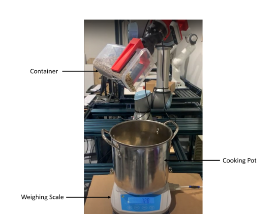
Fig 15. Robot pouring peanuts into the cooking pot
In addition to the PD controller, different kinds of shaking primitives are applied to the ingredient container during the dispensing process. These primitives aid in unsettling the contents of the container so that flow is smoother and continuous. The shaking primitives which are parameterized as sinusoidal profiles are executed alongside the PD controller in an asynchronous fashion.
In order to dispense different kinds of ingredients, the controller has different hyper-parameters which can be tuned to generate different kinds of behaviors. For example, some of the hyper-parameters associated with the PD controller are pouring axis, pouring about an edge or corner, and controller gains. The shaking primitives being sinusoidal trajectories have the typical parameters of such a parameterization like amplitude, frequency, etc.
Pouring a variety of ingredients that vary extensively in shape, size, and contour is a difficult feat to achieve purely through software. Hence, in order to make the control task simpler, we use containers with different types of lids for pouring different ingredients. For example, we use container lids with spouts for liquids, lids with holes for powder, and lids with slots for pouring different vegetables.
Fig 16. Different types of container lids
While a simple PID controller works reasonably well for most of the ingredients, the kind of behavior that the controller can exhibit is limited. In order to extend the capabilities of the PID controller, we utilize a framework called residual policy control where a secondary controller acts alongside a primary controller which provides offsets that act on top of the outputs of the PID controller. The secondary controller is parametrized as a neural network and is trained through reinforcement learning. The use of a neural network while enabling the controller to model complex behaviors also allows trivially incorporating other information useful to the pouring task (like tilt angle, and fill level) while making control decisions.
Fig 17. Residual Policy Control Framework
Integration
Software systems integration is simplified through the usage of ROS as the framework against which system components are designed. Components are implemented as ROS packages and are hosted over multiple machines to satisfy various platform and compute requirements.
When the system starts, we run the inventory update flow. The arm visits each location on the shelving unit, identifies each container by its AR tag, picks up the container (if present at that location), identifies the ingredient using visual and spectral (for visually confusing ingredients), measure the weight, and replaces the container back to the shelf correcting any pose errors and recording the final pose information to generate comprehensive inventory data.
Once the inventory data is generated, we run the dispensing flow. This enables the web server that can be accessed over the network at a designated URL which can be used to place a recipe dispensing request. Once a request is placed, the system verifies the inventory and immediately alerts the user in case sufficient ingredient quantities aren’t available. If not the system proceeds to dispense the ingredients into the cooking pot and prepare the recipe.
Once the dispensing is complete, the user is alerted via the web UI that his food is ready!
