1.0 Overview
For the PCB assignment, we have designed a setup that would act as a user interface for our robotic system. This includes an LCD screen that will list the available ingredients that the robot can dispense. It has two buttons and a knob (rotary encoder) to navigate through various options. The system closely resembles the interface that can be found on standard 3D printers. All the necessary electronics are powered and controlled by an Arduino Uno microcontroller. Since our system does not have any stringent size constraints, the PCB serves as a shield to all the required electronic components. This allows for a simple and modular design while avoiding the cumbersome task of using ICs to design the board from scratch.
2.0 Power Considerations
The power needs of our system are determined by the specifications of the following components
| S.No | Component | Current Consumption |
| 1 | Arduino | 30mA |
| 2 | LCD | 150mA |
| 3 | LEDs, Buzzer, etc | 20mA |
A detailed Bill of Materials can be found here.
3.0 Design Considerations
Standard 0.125” header pins (Male) with 3 Ampere tolerance have been used for mounting the Arduino and LCD screen on the PCB. Through-hole components have been adopted to facilitate easier assembly and debugging. To further enhance the ease of use, a 5mm red LED has been used for power status indication, a 5mm green LED for user indication, and a 5V buzzer for audio alerts.
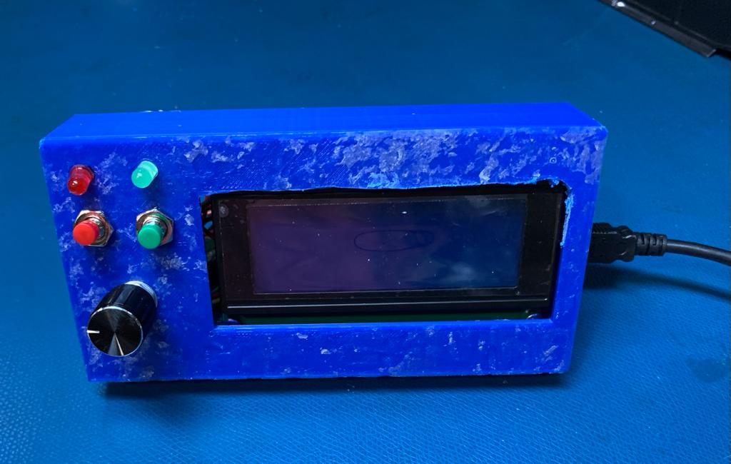
Fig 1. PCB assembled into the Casing
4.0 User Interface
The setup facilitates the user to select the ingredient and the weight of the ingredient to be dispensed. The ingredient names are displayed on the LCD screen. The user can cycle through the list of ingredients using the dial. One of the push buttons is used for making selections and the other is used to go back or revert the selection. After making the selection, the screen displays the quantity of the ingredient selected for dispensing as a horizontal bar. The corresponding numerical value of the selected weight shall also be displayed adjacent to the bar. The dial and push buttons are used to make the weight selection as done in the previous case.
One of the LEDs will be used to indicate the status of the system, that is, to indicate whether the system is currently active or not. The buzzer shall alarm the user whenever the system starts or ends an ingredient dispensing cycle.
Each time the system boots up the Arduino queries and stores the current list of items available for dispensing. Once an ingredient and an appropriate weight value are selected by the user, the request information is sent to the external computer.
5.0 Schematic
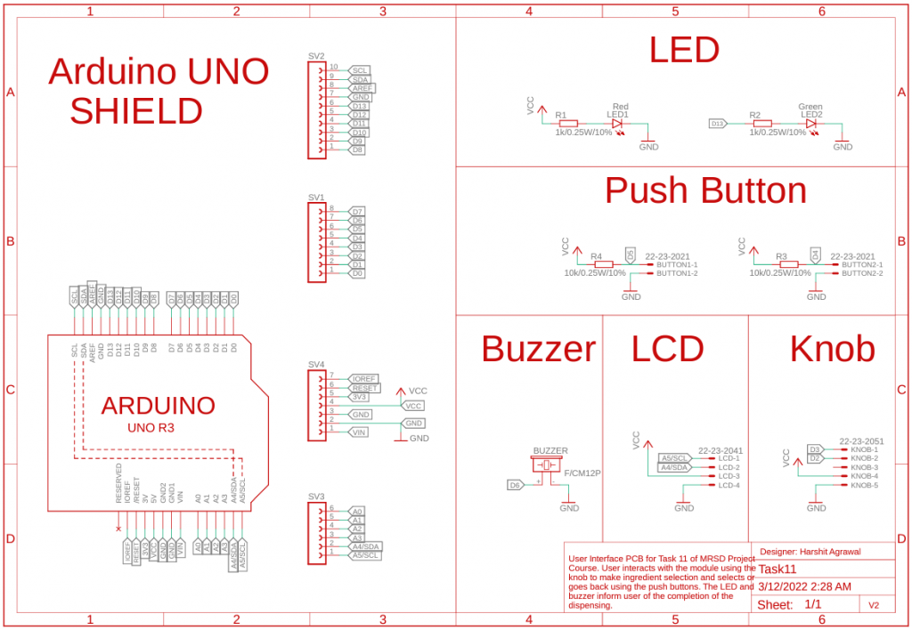
Fig 2. PCB Schematic
6.0 CAD Model
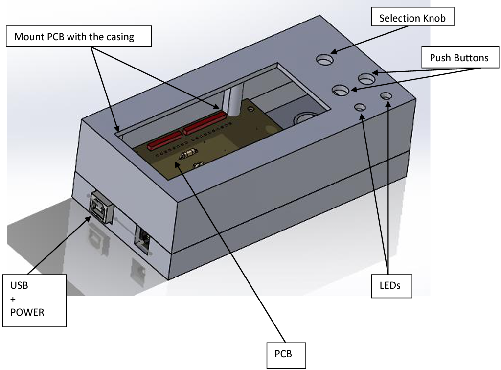
Fig 3. CAD Model of the casing
7.0 Board Layout
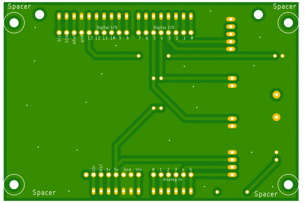
Fig 4. PCB Board Front
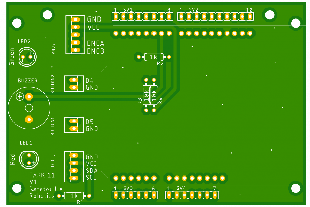
Fig 5. PCB Board Back