
Spring Subsystems
Localization
The localization subsystem determines pose of an agent given a map of the environment.| Inputs | Output |
| Initial estimated pose Occupancy grid map of environment Wheel encoder ticks Planar LIDAR range and bearing measurements | Robot pose |


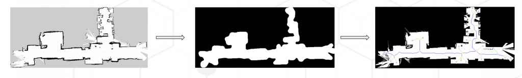
Task Generation
The task generation subsystem generates interest points or tasks for the robot to explore given an input map.| Input | Output |
| Occupancy Grid Map | Set of (x,y) nodes to be visited |
Task Allocation
The task allocation subsystem efficiently assigns each robot tasks such that all tasks are completed in minimal time.| Inputs | Outputs |
| Occupancy grid map n Robots m Tasks Robot initial positions | Next assigned task to robot i |


Navigation
The navigation subsystem generates path and velocity commands for all robots to complete their aThe navigation subsystem is responsible for generating paths as well as velocity commands for all the agents such that the agents are able to navigate to their assigned tasks while avoiding collisions with each other and traverse the environment in the shortest time possible.| Inputs | Outputs |
| Occupancy grid map of the environment Initial location of the agents Goal location of the agents | Velocity commands |


