PCB Layout
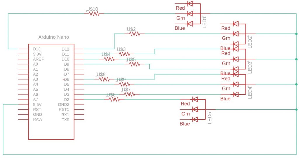
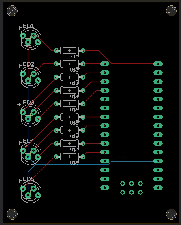
We designed a custom PCB containing RGB LEDs to show the status and the various modes of operation of the robot. These are connected to an Arduino Nano, which will be handling the status indication. The Nano is powered by the Xavier through USB.
The LED states are defined as:
- PWR LED: The power indication. This should light up if both the Xavier and the Arduino Nano are getting sufficient power to operate.
- HBT LED: The heartbeat indication. This is a light that will blink with a time period of 1.5 seconds provided that the ROS 2 pipeline is running. This can help us keep track of the online status of the hardware container on the Xavier.
- OPR LED: The operation mode indication. This will indicate the current one of the 3 operation modes.
- GREEN: Standby mode
- WHITE: Teleoperation mode
- BLUE: Autonomous mode
- TSK LED: The task mode indication. This will indicate the current one of the 4 task modes.
- GREEN: Idle mode
- WHITE: Navigation mode
- BLUE: Excavation mode
- RED: Dumping mode
- LCK LED: The lock status indication. This will indicate the current lock status of the rover’s actuation and mobility.
- OFF: Rover unlocked
- ON: Rover locked
The schematic and the board are shown in Fig. 1 and 2, respectively.