System Requirements
Mandatory Performance Requirements
| ID | Funcational Requirement | Performance Metric |
| M.P.1 | Receive commands from the user | The system will receive 2 types of commands: start/stop & desired configuration |
| M.P.2 | Map the terrain | The system will update the worksite map at a frequency of ≥ 0.1 Hz |
| M.P.3 | The system will output ≥ 2 data products of worksite map pre and post operation | |
| M.P.4 | Localize within the site | The system will localize itself within a positional accuracy of ≤ 30 cm |
| M.P.5 | Operate autonomously | The system will operate autonomously with 0 human intervention after the operation starts |
| M.P.6 | Traverse site terrain | The system will be capable of traversing a site terrain with ≤ 10 deg incline |
| M.P.7 | Excavate material | The system will be capable to excavate ≥ 3 kg material per cycle |
| M.P.8 | Build berm | The system will build a berm that has minimum dimensions of 15 cm in height and 30 cm in length |
| M.P.9 | The system will build a berm with an error tolerance within ±3 cm in height and ±5 cm in length |
Mandatory Non-functional Requirements
| ID | Non-functional Requirement | Description |
| M.N.1 | Appropriate Size | The system will have a size appropriate to the test site |
| M.N.2 | Maintain Traction | The system will be capable of maintaining traction during operation |
| M.N.3 | Environmental Robustness | The system will be able to operate in a dusty environment |
| M.N.4 | Safety Features | The system will operate safely (minimize human hazard) |
| M.N.5 | Evaluate Performance | The system will be capable of generating evaluation metrics |
Desirable Performance Requirements
| ID | Funcational Requirement | Performance Metric |
| M.P.1 | Receive commands from the user | The system will receive 2 types of commands: start/stop & desired configuration |
| M.P.2 | Map the terrain | The system will update the worksite map at a frequency of ≥ 1 Hz |
| M.P.3 | The system will output ≥ 10 data products of worksite map pre and post operation | |
| M.P.4 | Localize within the site | The system will localize itself within a positional accuracy of ≤ 10 cm |
| M.P.5 | Operate autonomously | The system will operate autonomously with 0 human intervention after the operation starts |
| M.P.6 | Traverse site terrain | The system will be capable of traversing a site terrain with ≤ 20 deg incline |
| M.P.7 | Excavate material | The system will be capable to excavate ≥ 5 kg material per cycle |
| M.P.8 | Build berm | The system will build a berm that has minimum dimensions of 20 cm in height and 100 cm in length |
| M.P.9 | The system will build a berm with an error tolerance within ±1.5 cm in height and ±2.5 cm in length |
Desirable Non-functional Requirements
| ID | Non-functional Requirement | Description |
| D.N.1 | Weight | The system will have mass < 100 kg |
| D.N.2 | Traverse Worksite Terrain | The system will maintain traversability of terrain throughout operation |
| D.N.3 | Technological Extensibility | The system will be well documented and designed so that future teams can easily access and build on the work |
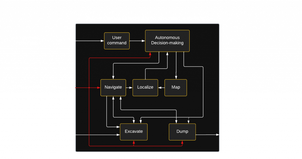
Functional Architecture
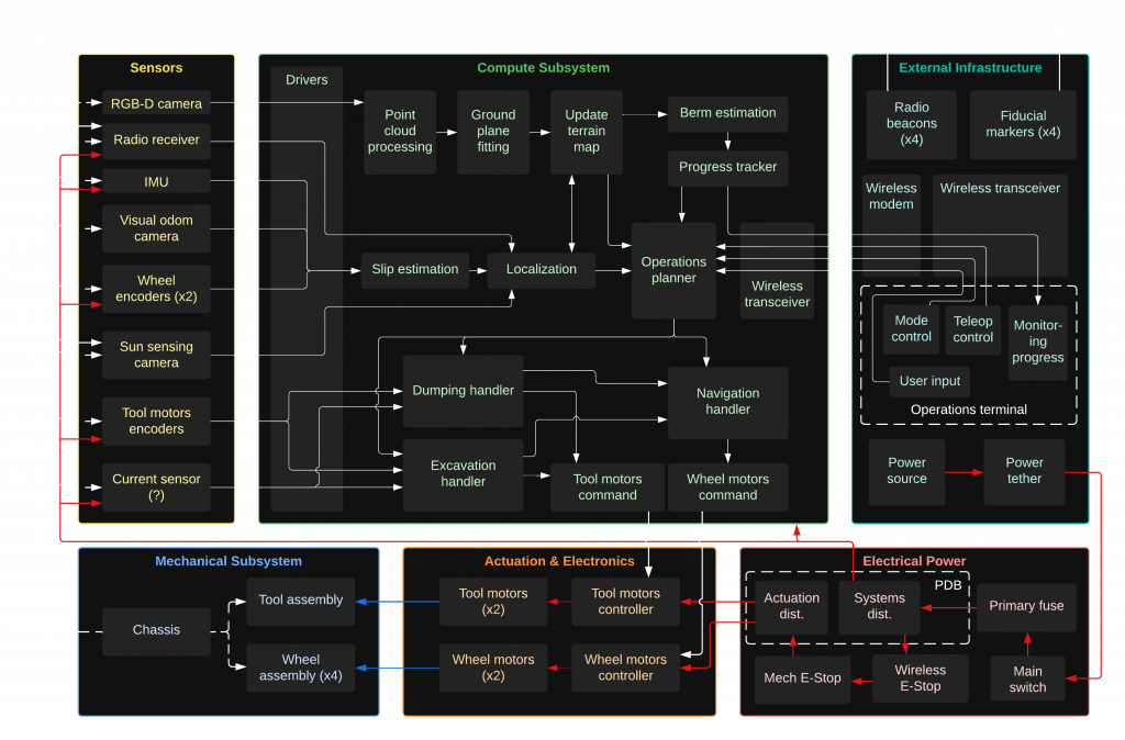
Cyberphysical Architecture
System Design Description
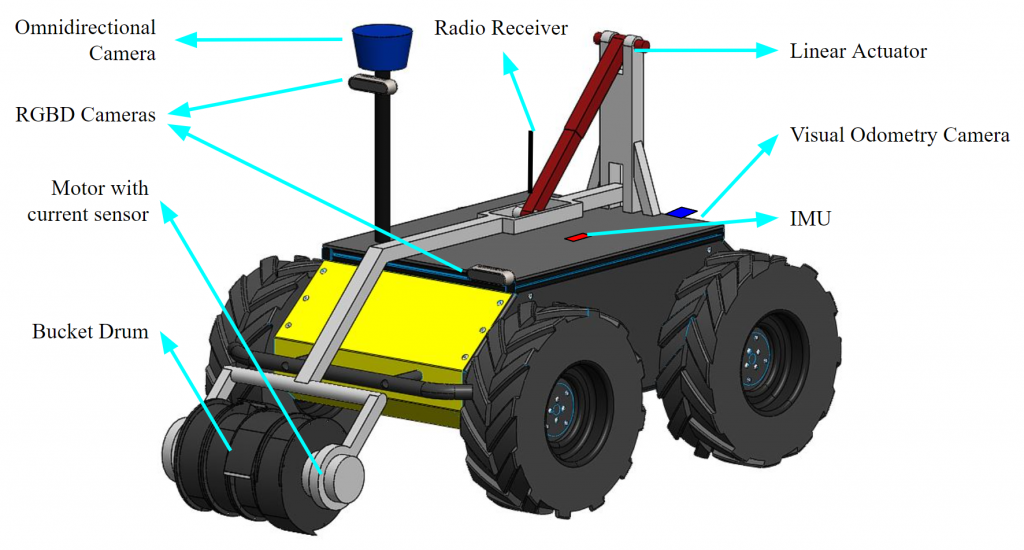
Rover
The rover subsystem will house all the sensors, tooling, and electronics necessary for the autonomous operation of the system. As per the trade study, the critical factors for choosing the rover/mobility platform include traversability, traction, and payload capacity. As per our trade studies, the Clearpath Husky A200 will be used as the mobility platform, while the Clearpath Jackal will be reserved as a backup. Figure above shows the mobility platform along with a preliminary design of the excavation tool and mechanism mounted. The sensors and electronics will be housed in enclosures to ensure robustness for operation in dusty conditions.
The Husky A200 platform is driven by a skid steer drive and has sufficient ground clearance to traverse over terrains well within the constraints set by the system requirements. The range of motion of the platform will be restricted to turns of high radius to maintain power efficiency and avoid sensor noise due to jittery motion. The platform is equipped with high-torque motors and wheel encoders. An external source will be used to power the platform to enable long-duration testing, eliminating limitations imposed due to battery life.
Tool
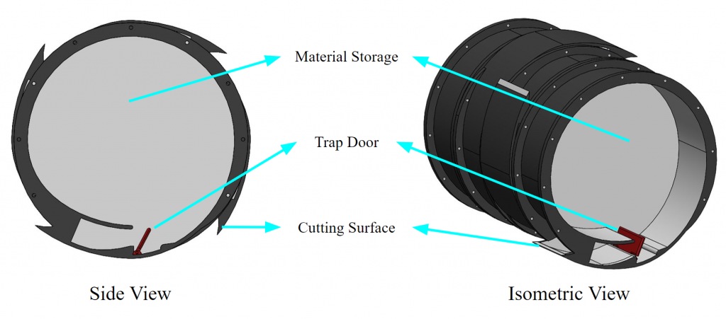
Maintaining low ground-reaction forces is crucial to excavation under low gravity conditions. Discrete excavation mechanisms can excavate large quantities of material per cycle, but they rely on high ground-reaction forces for success. Alternatively, continuous excavation mechanisms maintain low ground-reaction forces by reducing the contact profile with the ground. The continuous bucket drum mechanism was selected as a result of the tool trade study, and its preliminary design is shown in the figure. This mechanism is unique as it excavates when rotated in one direction and dumps when rotated in the opposite one. The design of this drum will be optimized by rapid prototyping techniques to better suit the system requirements. A fallback for the tool subsystem will include switching to the bucket.
The lifting mechanism for the tool has been designed to lift the bucket drum 0.5 m from the ground to allow the construction of the required berm size. A trade study between rotary and linearly actuated designs was conducted, and a linear pull-up mechanism was selected. It allows the use of lower-cost actuators while maintaining structural stability. The link lengths of the linear actuator and the mounting height will be optimized to reduce the force required. This is formulated as a min-max optimization, which minimizes the maximum force over the lifting motion. The preliminary design of the excavation tool and the lifting mechanism. The fallback mechanism design consists of a high-torque rotary drive.
Sensing
The sensing subsystem encapsulates all the sensors and feedback required for the system to perform the autonomous operation. It includes the various drivers, filters, mounts, and dust protection enclosures required for each sensor. A dual RGBD camera setup will be used to map the environment and estimate the built berm shape. Omni-directional camera mounted on top of the sensing mast will be used to detect and track fiducial markers to get absolute heading, emulating a sun-tracking solution. A visual odometry camera facing the ground will be used for slip estimation. An IMU sensor will be mounted at a position that will minimize exposure to vibrations due to system operation. Wheel encoders and tool position sensors will be used to determine the wheel velocities and the tool position. Fallbacks due to poorly performing sensors will include experimenting with different mounting locations (for cameras and IMU) and testing other sensor modalities (e.g., stereo camera or range sensors).
Software
The software architecture of the system is divided into the localization, mapping, planning, perception, and control modules. All components of the software will be implemented using the ROS2 framework. All sensor data will be subject to pre-processing. This will reduce noise in the data. Fallback algorithms for each subsection of the software module will be incorporated at a later stage when they are further developed.
The localization module will make use of the external radio beacons, sun sensing, wheel encoders, IMU, and slip estimation to localize within the work site. Slip will be estimated using a ground-facing visual odometry camera. Point cloud odometry will also be explored to increase the accuracy of localization.
To plan and re-plan autonomous construction operations, accurate measurement of the progress is required. This will allow for the planning of the subsequent dump and build poses. Two RGBD cameras, one mounted on a high vantage point and another mounted on the base platform pointed towards the expected berm location, will be used to generate a map of the surrounding areas. Ground plane fitting and berm shape estimation will be sequentially carried out to determine the progress.
The mid-level planning is split into three parts: the navigation planner, the excavation planner, and the dumping planner. The operations planner is the high-level planning module that can transition the system between the three states. The navigation planner will include a heuristic-based graph search planner that can plan a feasible path to the desired robot pose either for excavation or dumping. The excavation planner will plan the required depth of cut, the drum velocity, and the velocity of the mobile base to excavate material. The amount of material excavated will be calculated by performing current analysis on the tool motor. The dumping planner will use the dump pattern of the drum to determine the subsequent dumping pose and tool velocity for dumping the material in a manner that minimizes the berm construction errors.
The controls subsystem is responsible for tracking the desired tool and mobile base trajectories generated by the planning module. Sensor fusion output from localization and encoder feedback will facilitate closed-loop control and address external disturbances.
Localization and navigation planning modules will be validated on the Gazebo simulator before they are deployed on the system. An occupancy grid-based dumping planner simulation will be developed that uses a probabilistic model of the drum dumping pattern to validate the dumping pose generation algorithm.
External Infrastructure
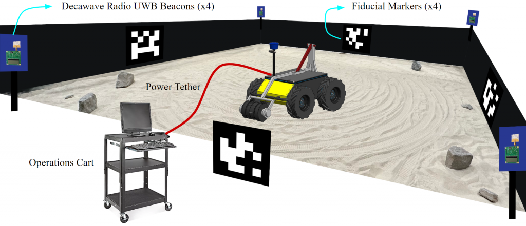
The external infrastructure is the combination of elements that are not onboard the system but are necessary for operation. It includes the operations terminal, interfaces for wireless communication, fiducial markers emulating the sun, and radio beacons to assist localization. It also includes evaluation tools such as a FARO laser scanner or an external RGBD camera to evaluate the final worksite configuration. Fallback for the operations terminal will include the use of personal computing systems with mobile wireless connections for communication.
Integration and Testing
The primary components of the integration and testing module are the documentation, facilities, apparatus, and procedures required for testing. Technical documentation entails the extensive and exhaustive test procedures for both the bench-level subsystem testing and the functional testing during integration. Facilities include the test site and the necessary testing infrastructure. The system will be tested at the Moonyard, a sandbox situated in the Planetary Robotics Lab at CMU, which is commonly used to test space robotic systems. Fallbacks will include nearby external test sites which retain the material properties found at the Moonyard.