System Requirements
The tables below summarize the high-level requirements which define Peter’s core functionalities and objectives. Each functional and nonfunctional requirement has been mapped to a performance requirement, determining how and to what extent these objectives will be measured. In determining these requirements, customer, stakeholder, and team interests were considered to create an effective and useful system. Each requirement is divided into two classes, mandatory and desirable, differentiating the base set of requirements from additional desirable ones. Performance requirements are subject to change through full acceptance from project stakeholders.
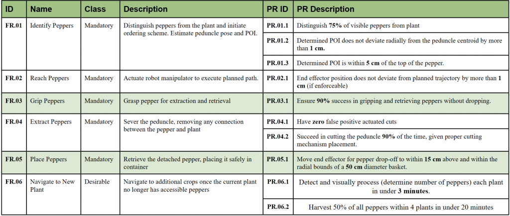
Functional Requirements:
An objectives tree was used to determine the functional requirements of the system, which are summarized in the table below. Peter shall first distinguish peppers from the plant (FR.01) and plan paths to the peppers while initializing a prioritization scheme. Peter then executes the planned path, placing the custom end effector at the determined pepper point of interaction (POI) (FR.02), grasping the pepper by the peduncle (FR.03), and extracting the pepper by cutting the peduncle (FR.04). Next, the pepper is placed in a basket near the base of the manipulator (FR.05). Peter shall then navigate along a pre-planned path to subsequent pepper plants in a row (FR.06).
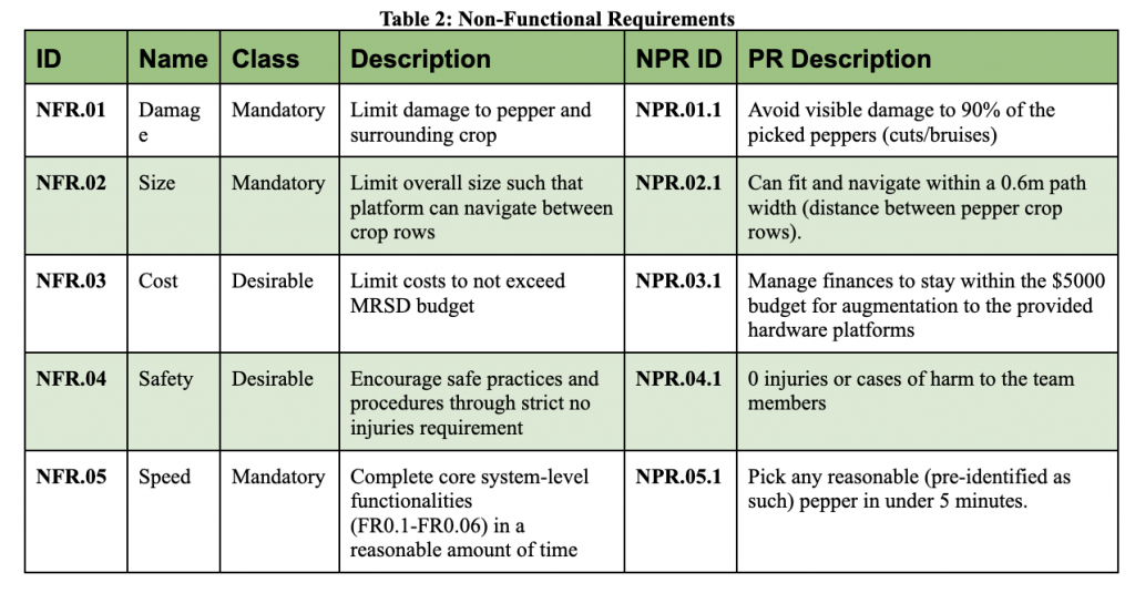
Non-Functional Requirements:
Key non-functional requirements have been included to ensure attention to stakeholder desirables and team non-negotiables that do not fit into the functional scope. These are summarized in the table below. The first requirement is to ensure pepper damage is minimized, as the harvested peppers need to appeal to the end consumer (NFR.01). The system should also have a proper size such that it can navigate through pepper crop rows (NFR.02). Development should not exceed the 5,000 dollar MRSD budget (NFR.03). It should not be conducted at the expense of the roboticists’ safety (NFR.04). Finally, Peter should harvest peppers in a reasonable amount of time, as to benefit farmers through efficient operation. (NFR.05).
Functional Architecture
The system’s functional architecture is depicted in Figure 2 below. The system receives both information and energy as inputs. Information enters the system in the form of before images of the pepper plant to be harvested, and energy refers to the electrical energy from the power supply. This facilitates the system to gain spatial awareness of the pepper plant from images and act on this knowledge to harvest peppers.
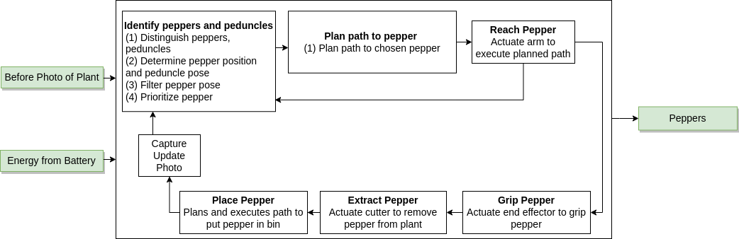
The system first identifies and segments peppers and peduncles. This block includes three crucial steps: characterizing the peppers and peduncles, filtering multiple detections, and selecting the POI (point of interaction). At this stage, information about the spatial pose of the pepper set (fruit and peduncle) relative to the arm base frame is calculated. The peduncle’s orientation is also calculated during this process to allow the system to harvest peppers in the real farm environment. The system performs a multi-framing movement where the manipulator’s arm makes a vertical movement for multiple detections of the pepper set. When the system has multiple sets of pepper and peduncle matches, they are passed through the Kalman Filter node, where the pepper gets prioritized based on a few metrics such as the distance to the base of the arm, the number of detections, and the confidence rate of the pose of the pepper set. This function ensures that the system will not try to harvest a sparse, false positive pepper detection and that the harvest happens in a reasonable order.
After obtaining relevant information about the plant and its peppers, the system will plan a path to a POI pre-grasp position. This process is executed with the awareness that the system should not cause irreparable damage to the plant, as doing so would impair future harvests. Once the proper path to the pepper is planned, the arm initially moves to a pre-grasp position that is 15 cm away from the pepper of interest by following the generated path. After, the arm makes a cartesian movement that goes straight in, thus placing the end effector in position to start the gripping and cutting process.
Once the pepper has been reached, the end effector will grip the pepper. Gripping the pepper with reasonable force is essential to ensure the proper delivery to a basket. To guarantee this behavior the end-effector includes a feedback loop to guarantee this behavior. This ensures that the system gains insight into how suitable its grip on the pepper is. If the POI calculation is inaccurate or any unexpected behaviors lead to the end effector not being placed properly at the peduncle, the gripper uses current feedback to not actuate the cutting mechanism. This ensures the system behaves efficiently, reducing unnecessary time needed for harvesting unless a peduncle is present in between the grippers. If the pepper is effectively gripped, it’s extracted by actuating the cutting mechanism.
After successful extraction, the arm moves backward cartesian and goes to the basket position for drop-off. There, the gripper releases the pepper, which is placed in a basket. At this point, one singular pepper will have been harvested. Ensure all peppers have been collected, and the steps mentioned above are repeated until all accessible and visible peppers have been harvested.
When no peppers are detected on the plant in front of the robotic system, the GUI informs the driver to drive to the next plant to harvest. The driver is responsible for moving the Amiga platform until they reach the next Aruco marker and start the harvesting process again. The outputs are two-fold: green peppers and an updated photo of the pepper plant. The collected physical peppers and images can confirm a successful harvest.
Cyberphysical Architecture

The cyber-physical architecture of the system was developed from the functional architecture and trade studies. The architecture has seven blocks: detection, manipulation, power, trajectory generation, navigation, sensing, and environment. The black arrows represent the flow of data and information, the green arrows show feedback, the red arrows indicate the flow of electrical energy, and the blue arrows depict the flow of mechanical energy.
The flow of this cyber-physical architecture begins at the Amiga base platform in the Navigation block. Once the mobile base is positioned in front of a plant, the RealSense D435i camera in the sensing block and robotic arm motion of up and down in the manipulation block are activated. Images from this camera mounted on the arm are sent to the detection block. A YOLOv8 model will provide the masks and bounding boxes of pepper fruits and peduncles in the image. 7D poses representing the positions and orientations (in quaternion form) of the peduncles are then calculated.
A pose filtering block will smoothen the noisy pose estimates. These peppers are prioritized based on heuristics to choose a single pepper. A path is planned to the pre-grasp position that lies in front of the chosen point of interaction. After successful execution of the generated path, the arm is moved forward to accurately place the end-effector at the point of interaction. Now, the gripper driver signals the Dynamixel motors to first grip and then cut the pepper. The cutter is only actuated based on grip feedback to ensure zero false positive cuts.
Next, the manipulator follows a retrieval trajectory, and the pepper is then placed in the basket. After all the peppers within the view of the camera have been removed from the plant, the navigation subsystem moves the mobile base to a new location, at which point the entire process of identifying and extracting peppers is repeated.
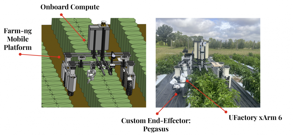
System Design Description
The overall system consists of the testbed setup and each of the individual subsystems. Figure 4 below shows a graphical depiction of the overall system. We used the Amiga mobile base platform by Farm Ng. We attached the UFactory xArm6, which is a 6 DOF arm for our manipulation subsystem, to the mobile base platform. Attached to the arm is the custom end-effector for cutting and gripping. Mounted to the end-effector is the Intel RealSense D435i Camera.
Peter can identify peppers and harvest peppers from a row of green pepper crops. The image below shows the testbed setup from our Fall Validation Demonstration, which took place in the Newell-Simon Hall basement at CMU. We built a testbed to hold four fake plants. Each plant had two real peppers attached to it. Each real pepper had an artificial peduncle made with celery. Because it’s difficult to find real peppers with peduncles still attached in the grocery store, we had to artificially create peduncles using celery, which is a close visual representation of actual peduncles. Aruco Markers were placed next to each plant in order to inform the driver of the robotic system when a new plant has been reached, so they can stop moving forward. A basket was attached to the Amiga mobile base platform for holding the harvested peppers. Figure 5 below shows the full testbed setup.

Perception Subsystem
The perception subsystem encompasses three major tasks: detection of peppers, calculation of peduncle pose, and the ordering pattern for peppers. The detection of peppers and stems is done using YOLOv8, which outputs the segmented locations of the objects.
The computation of poses of detected peppers and peduncles uses the data from the RGB-D camera sensor and the outputs of the detection algorithms. With the information of each pepper and the state of the robot, the order in which the peppers should be picked is chosen. The perception subsystem’s performance relies heavily on the manipulator subsystem as the camera’s view would be less occluded once it is closer to the pepper. Thus, most of the detection process is iteratively executed as the location of the manipulator changes.
A more recent addition is that of a filtering behavior that works closely with the perception subsystem. Not only does it smooth estimates, but it also uses predefined hyperparameters to aid in error rejection of false detections made by our YOLOv8 network.
End-Effector Subsystem
The end effector subsystem encompasses the mechanical design, fabrication, and control of Peter’s method of interaction with a given pepper plant. The described interaction includes two main processes: grasping the pepper and severing the peduncle. The current approach is to interact with the peduncle directly, pulling the pepper along with the grasped peduncle. Components of the end effector subsystem include mechanical components such as gear boxes, electrical components such as motors and drivers.
We created a prototype that could grip, and then tested and refined it until we were satisfied with its stability and efficiency.
As we continued our development, we realized that we could optimize the end-effector’s performance by splitting the original gripping function into separate cutter and gripper modules. This approach allowed us to refine each module independently, ensuring that they were optimized for their specific function and could operate at peak efficiency.
Once we had refined the cutter and gripper modules, we integrated them back together to create a final design that exceeded our expectations. Using this spiral approach, we were able to constantly incorporate feedback and make adjustments as we went along, resulting in a high-quality and efficient end-effector. A summary of our iterations can be found below.
| Iteration | Summary | Visualization |
|---|---|---|
| 1 | Strengths: – Kinematic Understanding of Mechanism – Understanding of Form Factor & Places to Improve – Little Time and Effort to Gain Information Weaknesses: – Low Torque Transmission – Improper Alignment of Pads – Immature Electronic Circuit | 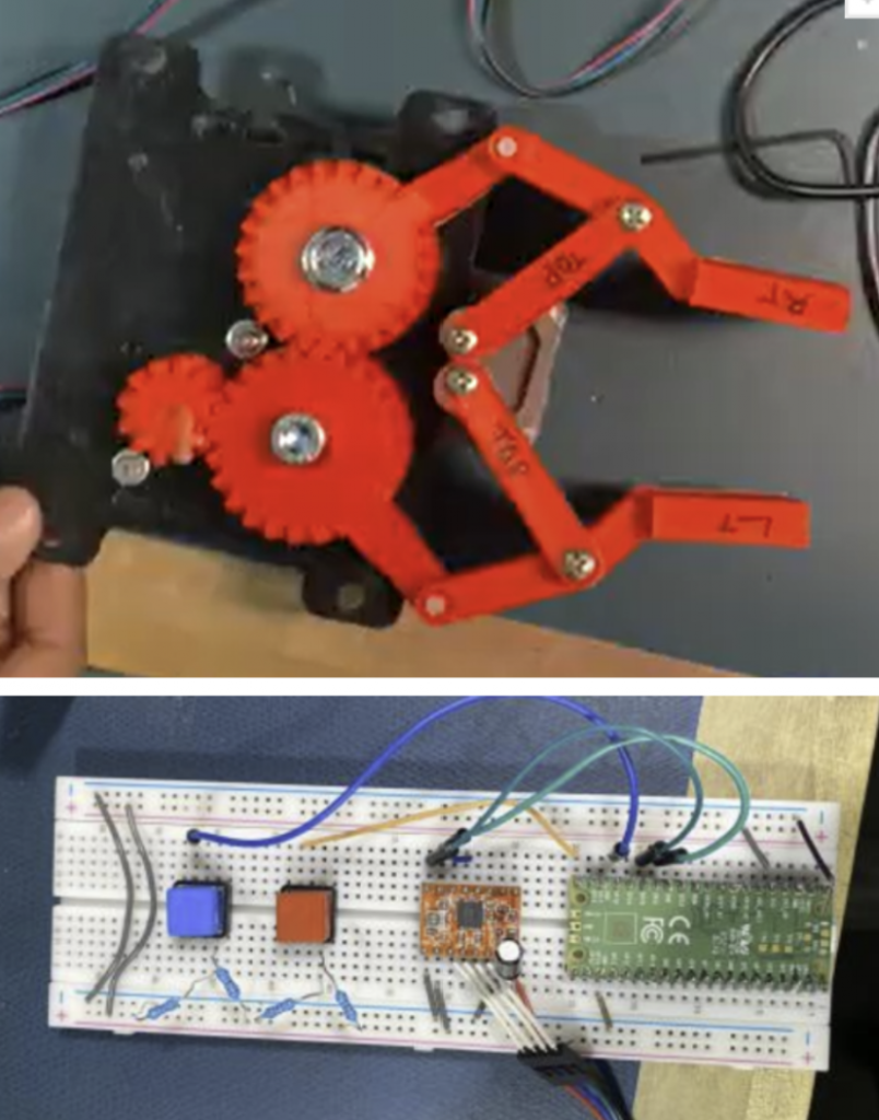 |
| 2 | Strengths: – Improved Alignment and Torque Transmission Weaknesses: – Large Form Factor – Flaring of Gripping Pads – No Compliance in Grip | 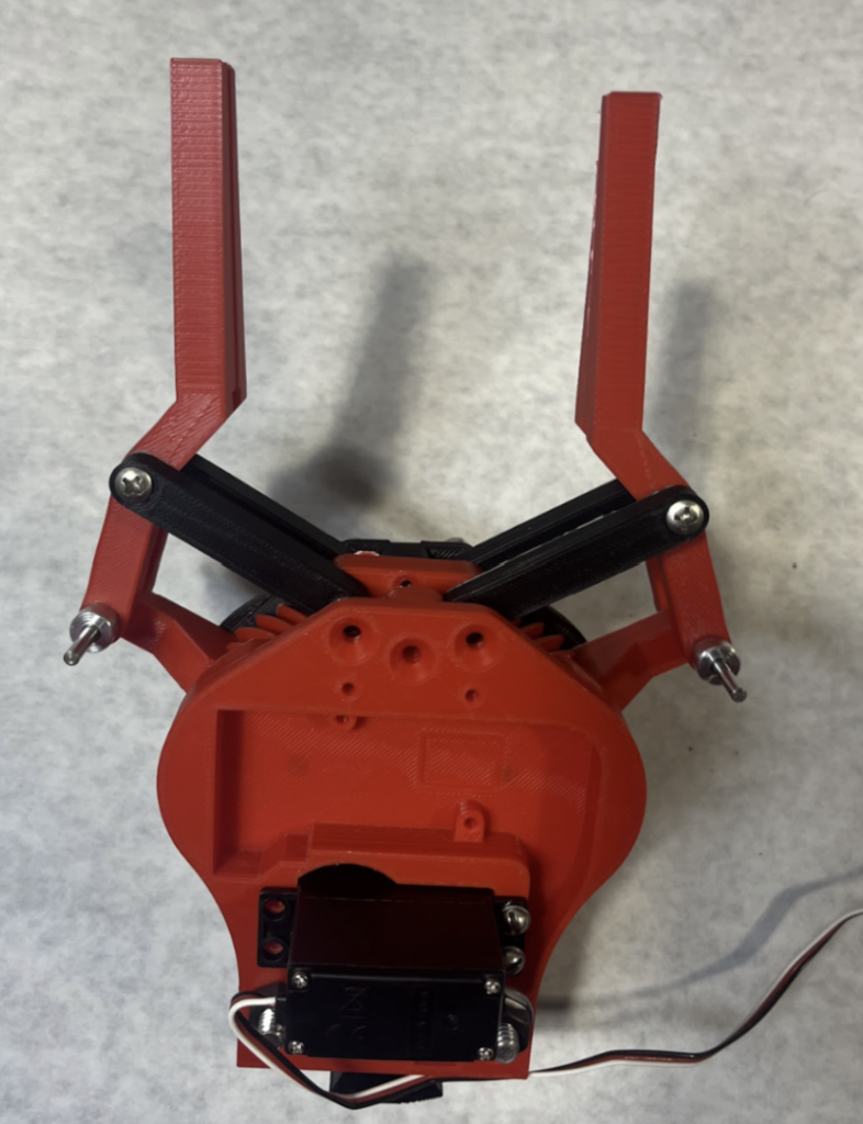 |
| 3 | Strengths: – First Integration of Cutting Design – Improper Force to Cut Peduncle – Cutting Design that funnels peduncle towards blade – Removal of three-tiered link Weaknesses: – Large Form Factor – Rails made printing Difficult | 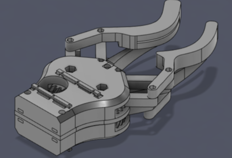 |
| 4 | Strengths: – First Reliable Cuts at close and mid positions – Angled blades on both sides centralized force similar to scissors – Reduced unactuated link length increased force transmission at the blades Weaknesses: – Rails created undesirable prints – A lot of friction led to force dissipation – Helical blades caused out of plane force transmission during gear lockout | 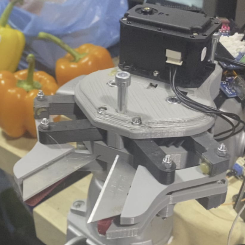 |
| 5 | Strengths: – First Reliable Cuts along length of blade – Introduced brass tubing, shims, and washers reduced friction for more efficient force transfer – Use of heat inserts increased print qualities – Camera mount rigidly fixed camera to end-effector – Sharpened blades increased cutting performance Increased gear ratio (2 to 3) Weaknesses: – Unreliability of electronics and immature control scheme may need to be reevaluated – Long-term strength of geared components needs to be watched | 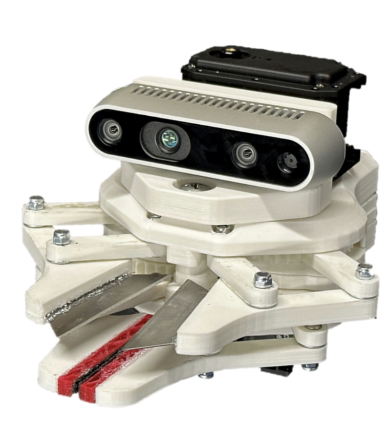 |
| 6 | Material upgrades to steel & brass gearing, to prevent the risk of gear teeth from cyclic damage. | — |
Motion Planning Subsystem
The motion planning subsystem provides the connection between the perception subsystem and the end-effector subsystem. The motion planning portion involves taking information from the perception side to place the arm in optimal locations. This subsystem also ensures that the arm will avoid any generated constraints to avoid plant damage.
The perception subsystem will determine the peduncle positions and optimal end-effector pose as well as the locations of any constraints, which the arm should not pass through, such as the stems of the plant or other peppers on the plant. With this information, the final position of the arm will be computed. Our current planning system directly operates with UFactory xArm’s SDK to perform workspace and cartesian moves.