System-Level Integration

A robust finite state machine controls high-level decision-making of our system. It starts and terminates the different states in our system as shown in the figure above. In the Spring semester we had a much more complicated state machine with multiple pieces of back and forth communication between subsystems through the use of many ROS services. In the Fall semester we greatly simplified our state machine and parallelized all operations. Now all subsystems are continually running while the high-level task planner and state-machine handle the decision-making. For example, the perception subsystem constantly publishes detected POIs despite of which state the system is in. In the Spring, the perception subsystem would only provide one POI when requested for it by the manipulation subsystem. Making all operations parallelized and continuous greatly simplified our architecture and made it much easier to debug.
Our system has manual operation states which allow the user to provide input by pressing buttons on the joystick controller. There are three manual operation states: idle, teleoperation, and visual servo. In the idle state, all operations are paused. The only action that can be performed in this state is teleoperating the Amiga mobile base platform. Switching the system to teleoperation mode allows for manually controlling the xArm through the joystick controller. The visual servo state will run the perception stack and command movements to the arm to align a detected pepper in the center of the camera.
The autonomous operation states make up the pipeline for our pepper harvesting procedure. The state machine automatically cycles through these states in order to harvest peppers. The arm starts in an initial position then scans the plant to obtain detections. If a pepper is found, the arm moves to a pre-grasp pose, then moves to the POI for grasping. At this point a pepper is harvested and then dropped off in the basket. Finally, the arm moves back to the initial position and the cycle repeats until no more peppers are detected on the plant at which point the system transitions to the idle state. Gripping feedback is also handled by the state machine as the arm will move back to the initial position after harvesting rather than to the basket if the pepper is not being gripped by the end-effector.
Perception Subsystem
The perception subsystem encompasses four significant tasks: the segmentation of fruits and peduncles, matching fruits with their peduncles, calculation of a 7D pose of the point of interaction on every matched peduncle, and finally passing the poses to the filtering node.
The segmentation of fruits and peduncles are done using YOLOv8, which outputs the segmented masks of the desired objects. There are two different models for the outdoor environment and the indoor environment. Each of the segmentation models were trained on about 7,000 green bell pepper images to achieve a mAP50 of 0.8. Once the fruits and peduncles are detected and segmented, it goes to the pepper matching stage.

The pepper matching process is conducted in multiple steps. First, we retrieve all the fruit and the peduncle locations. We calculate the distance between a fruit centroid and all peduncles to find the peduncle closest to the fruit. Once we have a potential match, we check if the peduncle location makes sense relative to the fruit location. Peduncles that are on the side/bottom of the fruit are filtered out. Once we run this matching process multiple times for each fruit in the frame, we have a pepper match consisting of a pepper fruit and a pepper peduncle. The visualization below associates each pepper and peduncle match in the same color.

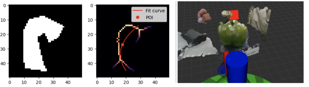
YOLOv8 provides the segmented peduncle’s boundary points, which is converted to a black and white mask as shown in the first plot. The medial axis of the segmented mask is obtained with the help of the Python Skimage package and is shown in the second plot, represented by the colorful points. A parabolic curve is fit to the points on the medial axis. A least squares error between the points on the medial axis and the points on the fit curve is used as a metric to decide if the parabola is oriented vertically or horizontally. Subsequently, a point of interaction is calculated at a distance of half the total curve length from the top of the pepper fruit. This is a 2D point on the image, which is converted to a 3D point in space using the depth data provided by the RealSense camera. Lastly, the determined 3D point is verified by visualizing both the point cloud data of the environment and the point of interaction in RViz (in the RealSense coordinate frame).
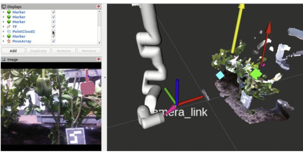
Another point that is at a distance of 70% the total curve length from the top of the pepper is obtained. This point is called the next point. Both the 3D position of the POI and the next point are converted from the RealSense coordinate system to the base frame. A vector starting from the point of interaction and ending at the next point is estimated as the peduncle’s pose. The perception subsystem constantly publishes poses of every matched peduncle in the image. These poses are represented by a 7D vector, consisting of a position and an orientation in the form of a quaternion.
As the perception node is running constantly, we command the manipulator to perform a vertical up-down movement to obtain multiple estimates of each matched peduncle’s pose in the base frame. This process of detecting peppers and estimating POIs while moving the arm up and down is called the multi-frame process. Throughout the motion of the arm, 7D poses are published to the pepper filtering node.
Kalman Filter Routine
During the aforementioned multi-frame routine, numerous localizations of the POI in the world frame are generated. These detections are accumulated and filtered using the FilterPy implementation of a Kalman Filter. This POI is specified as a vector in 3D space (Figure 12). The state for this filter includes an XYZ localization, along with the orientation of the vector as a quaternion.
A nearest-neighbor approach using a Euclidean distance is used to associate detections of peppers from frame to frame. If a cluster of POIs either does not obtain a new detection within a predefined amount of time or if it does not have enough observations after a predetermined time, then the cluster is removed. These criteria allow us to lightly filter false positive detections given by the Yolov8 network. The last crucial aspect of the filter’s capabilities is its ability to prioritize peppers. While rudimentary, the peppers are merely sorted by the number of observations of each pepper. In this way, Peter harvests the peppers it is most confident in existing. In the future, we anticipate a more complex heuristic, such as a combination of distance to the end-effector and observations could yield additional advantages. This would allow for the harvesting of the closest peppers that it is most confident in.
End-Effector Subsystem
Mechanical Design
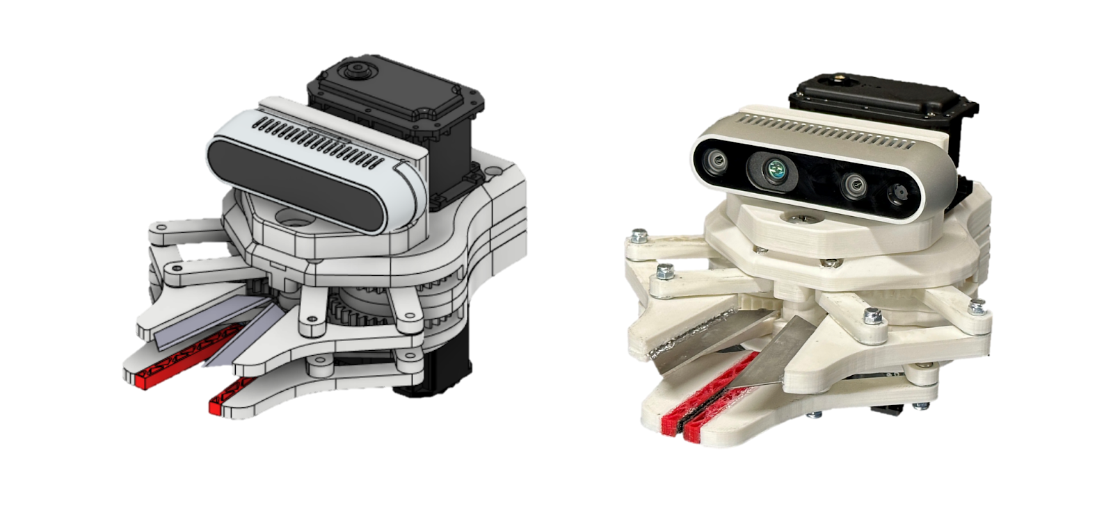
In developing our end-effector, we balanced the following design considerations: form factor, force transmission, modularity, and error handling abilities. Our approach to harvesting green bell peppers is to directly grip and cut the peduncle of the plant, with the assumption that our peduncle would be mostly straight (at least 5 cm) and orthonormal to the surface of the top of the bell pepper. Additionally the design of the end effector has only 2cm of vertical separation between gripping and cutting mechanisms, enabling a significantly shorter peduncle to be harvested given an accurate POI. Through on-site testing at an Ames, Iowa farm, it was determined that this assumption is only applicable to ~40% of peppers. The remaining portion of peppers either have levels of occlusion such that any camera system would have difficulty identifying the fruit, or are growing in an awkward configuration too close to the main stem to be reliably harvested. Still, the end effector had a high level of success in harvesting peduncles under the expected conditions outlined above. The final product, PEGASUS (Pepper Extracting and Gripping Assembly for Ultimate Success) is shown below.
The end-effector features two modules: a gripping unit and a cutting unit that are both actuated via Dynamixel Motors. Both units share identical mechanisms: a four-bar linkage mechanism driven with a gear train. We designed around the cutting unit, assuming that generating the required force to cut a peduncle would translate well to the gripping task. During the development of both modules, critical changes in the development included the addition of a washer and shims to reduce surface friction, plating the inner surface of links with brass to reduce the friction of the M3 screws that act as shafts, angling the cutting blades, and reducing the length of the grounded, unactuated link.

The most significant change to the end effector over the fall semester was a material upgrade. The pinion which interfaces with the dynamixel motor was upgraded to brass and the geared links which interface with the cutter links as shown in Figure 14 were upgraded to stainless steel. The material selection of brass and stainless steel was aimed at increasing strength, rigidity, and corrosion resistance. When compared to 3D printed parts, the materials exhibit stark performance gains across each of these categories.
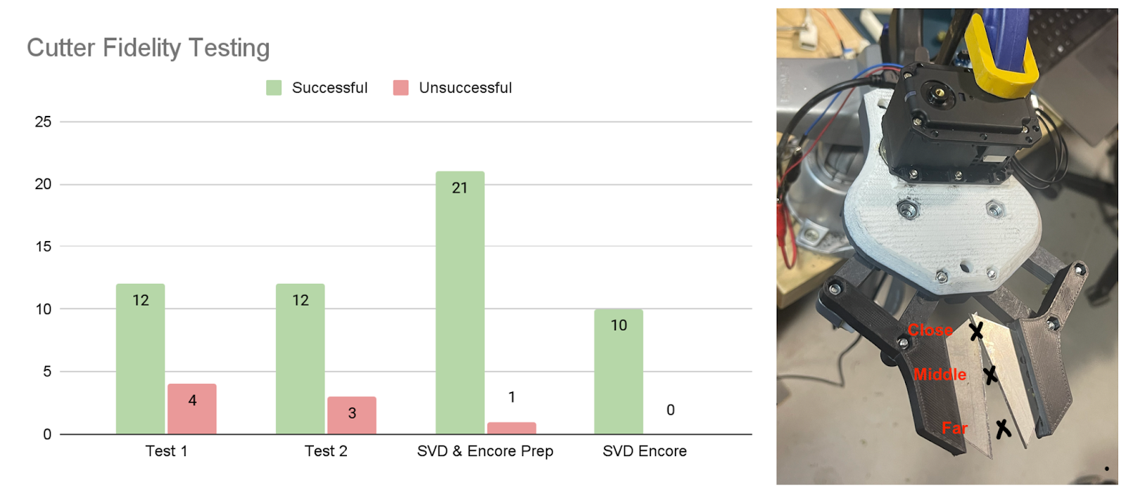
Prior to these changes, subsystem level cutter fidelity testing (Figure 15) was conducted. This unit test included recording the diameter of the peduncle (which ranged from 5mm – 11mm), total current drawn, and the rate of cut successes. Cuts were performed at the close, middle, and far positions (depicted in Figure 15) to inform us how our end-effector would handle any compounded errors between the perception and manipulation subsystems.
Control & Electronics
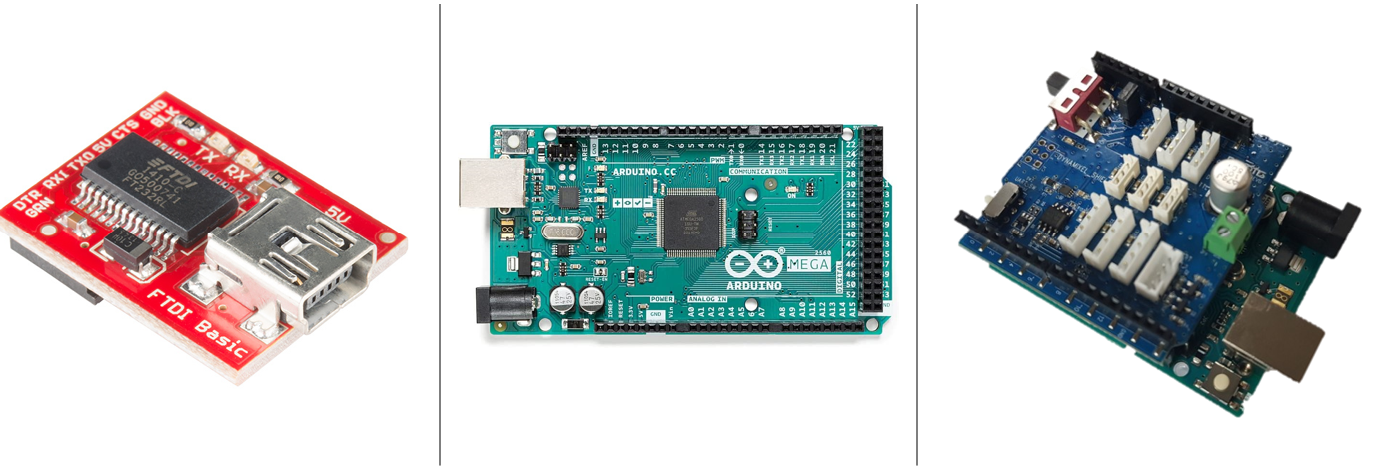
During the spring semester, motor control methods were implemented and sent to the end effector using the Dynamixel Shield, its associated library, and an Arduino Mega running rosserial, all shown in Figure 16 below. An FTDI chip converted the USB signal from the computer hosting the ROS master to serial, which could then be read into the Dynamixel Shield/Arduino and trigger behaviors on the dynamixel motor of the end effector. Hand-tuned open and close positions were used to define gripping and cutting motions, which were built into ROS services accessible to the main system. These motion schemes were built by implementing a position controller utilizing the built-in encoder of the motor. However, undiagnosed component failures were observed during the spring semester demo, and thus the assembly of electronics was deemed not robust at the system level.
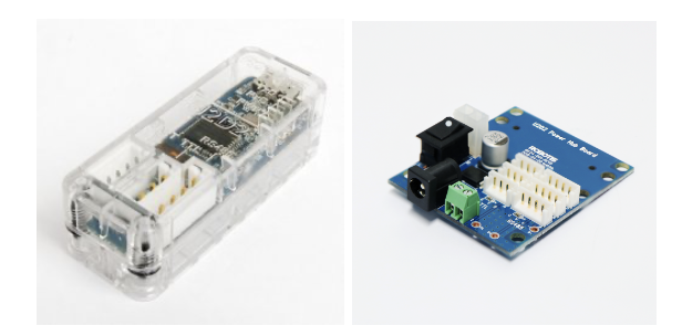
Going into the fall semester, it was decided to do away with the arduino mega, microROS, FTDI chip, and associated electronics in favor of proprietary dynamixel connectors and PCBs. The end effector control stack was vastly simplified with only two electrical components in between the dynamixel motors and the laptop hosting ROS, the dynamixel U2D2 and power hub shown in the figure below. The same motor functionality was able to be implemented with improvements via dynamixel API calls, and it was significantly easier to debug any faulty behavior with fewer intermediary electronics present. Two additional features developed for the end effector subsystem include autonomous calibration on startup and current feedback on grip attempts. The former removes the need to manually set open and close positions for the gripping and cutting mechanisms and the former is able to confirm if a pepper is actually present to be grabbed at the provided POI, negating false positives.
Manipulation Subsystem
The manipulation subsystem provides the connection between the perception and end-effector subsystems. This subsystem involves taking information from the perception computations to place the arm in optimal locations. This subsystem also ensures that the arm will avoid collisions with the environment. In the Spring semester, the Kinova Gen3, which is a six degree-of-freedom arm made available through the Tepper AI Makerspace, was used for manipulation. However, in the Fall semester the team transitioned to using the UFactory xArm6, which is also a six degree-of-freedom arm.
Originally, the Open Motion Planning Library (OMPL) within MoveIt was utilized in the Spring semester with the Kinova arm. We specifically used the RRTConnect algorithm from OMPL. We originally decided to use MoveIt for planning purposes because we wanted to develop an arm-agnostic planner due to our lack of access to a manipulation platform. However, once the final arm was determined as the UFactory xArm6, we chose to leverage the capabilities of the xArm API. MoveIt proved to be unreliable and slow when planning in a highly constrained environment. The xArm API allowed for easy and robust planning for our application and also allowed for faster planning times.
The arm goes through a series of trajectories to successfully extract a pepper. The motion planning subsystem is heavily connected to the high-level state machine and task planner. Depending on the current state of the autonomous harvesting procedure, the arm completed different maneuvers. The arm begins by moving to the initial position. This position was experimentally determined as an ideal pose for viewing the entire plant as well as ensuring the peppers on the plant are within the workspace of the arm. Then, the arm scans up and down the plant, as part of the “multi-framing” process. Multi-framing allows for an increased number of detections of the pepper and peduncle to increase accuracy of the final chosen POI. As the arm is scanning the plant, the perception subsystem publishes smoothed POI estimates for the manipulation subsystem.
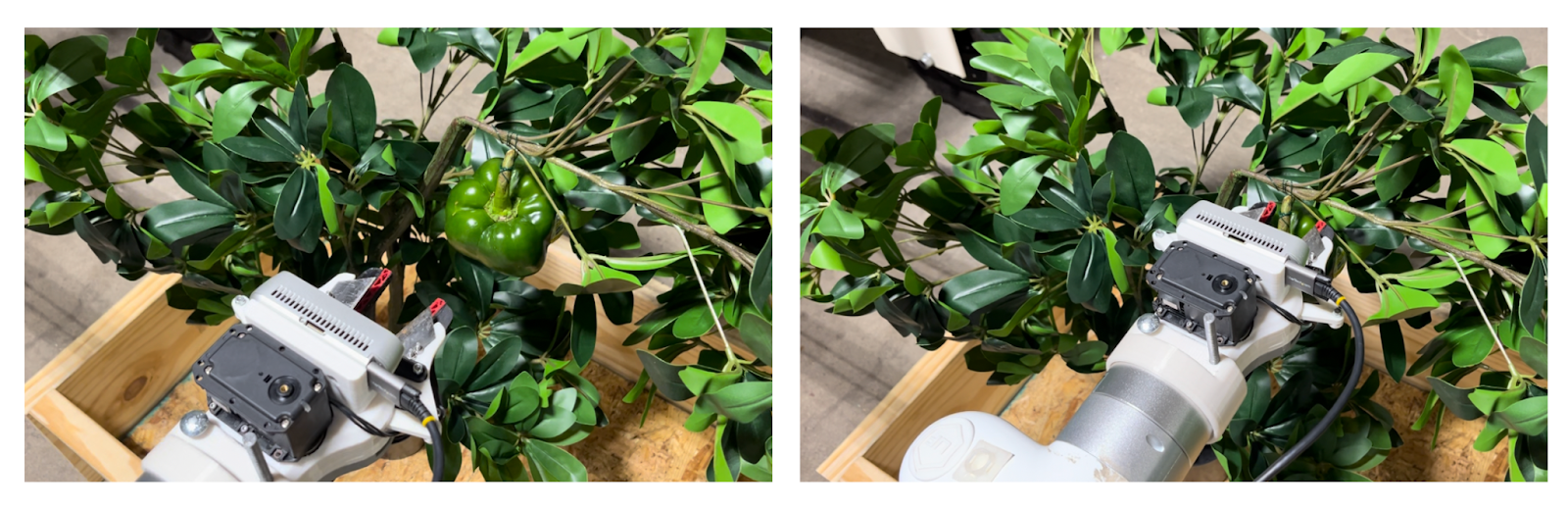
Once multi-framing has been completed, the POI estimate is used to determine an ideal pre-grasp pose which the arm moves to. From the pre-grasp pose, a cartesian move along the depth axis only is executed to move to the final grasping position. The image below shows the arm in the pre-grasp and final grasp positions. At this point, the end-effector subsystem grips and cuts the pepper from the plant so that the arm is holding the extracted pepper.
Handling peppers hanging at different orientations was explored for the FVD Encore. Handing oriented peppers was outside the scope of our FVD requirements, but were handled as a stretch goal. If a pepper is hung at an oriented position on the plant, the manipulation subsystem can optionally use the information from the perception subsystem in order to accurately add roll to the grasp pose of the arm. The image below shows a view of RViz in which the grasp pose is aligned with the vector showing the orientation of the peduncle.

After the pepper has been successfully extracted, a cartesian move is executed again to move backwards away from the plant. Finally, a series of trajectories are completed to drop the pepper off in the basket and move back to the initial position. These longer trajectories are executed by following a set of predefined waypoints to and from the basket. At the basket, the pepper would be released and the arm would move back to the initial position. Then, the process would repeat until there are no peppers detected during multi-framing at which point Peter would move on to harvesting the next plant.
One of our performance requirements (PR.03.1) was to ensure that the end-effector position does not deviate from the planned trajectory by more than 1 cm. We were able to succeed in this performance requirement by accurately moving to the POI provided by the perception subsystem and following the planned trajectory throughout the move. Testing was also performed to validate this requirement. We chose randomized POI locations and measured the difference between the desired and actual end-effector positions.
After a pepper is extracted, the arm moves to the basket drop position to release the pepper. This movement allows us to meet our performance requirement PR.06.1: move the end-effector for pepper drop-off to within 15 cm above and within the radial bounds of a 50 cm diameter basket. All performance requirements for this subsystem were successfully met and completed during testing as well as during the Fall Validation Demo (FVD).