End-Effector Subsystem
Mechanical Design
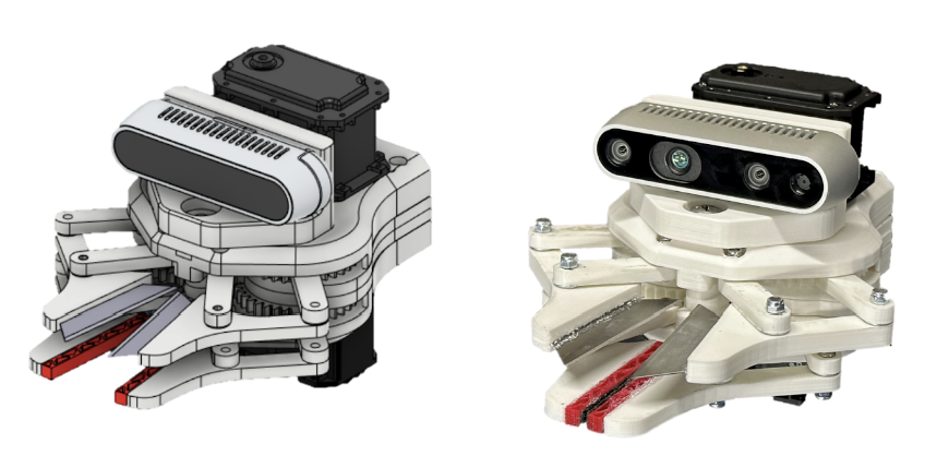
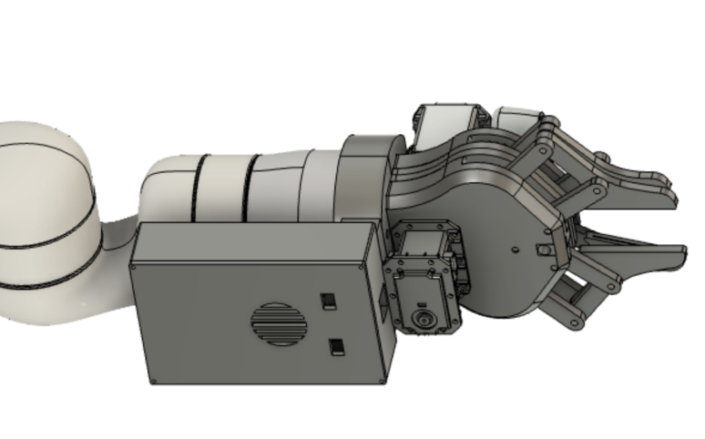
In developing our end-effector, we balanced the following design considerations: form factor, force transmission, modularity, and error handling abilities. Our approach in harvesting green bell peppers is to directly grip and cut the peduncle of the plant, with the assumption that our peduncle would be mostly straight(at least 10 cm) and orthonormal to the surface of the top of the bell pepper. Onsite testing in an Iowa-based farm will need to be conducted to verify our assumptions. The final result, operating under our current assumptions, is shown below.
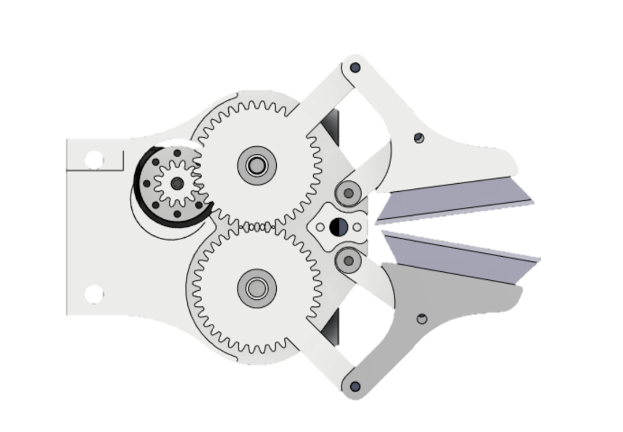
At our current stage, the end-effector features two modules: a gripping unit and a cutting unit that are both actuated via Dynamixel Motors. Both units share identical mechanisms: a four-bar linkage mechanism driven with a gear train (below). We designed around the cutting unit, assuming that generating the required force to cut a peduncle would translate well to the gripping task. During the development of both modules, critical changes in the development included the addition of a washer and shims to reduce surface friction, plating the inner surface of links with brass to reduce the friction of the M3 screws that act as shafts, angling the cutting blades, and reducing the length of the grounded, unactuated link.
All of these changes were made before completing our cutter fidelity testing (below, right). This unit test included recording the diameter of the peduncle (which ranged from 5mm – 11mm), recording the total current drawn, and recording the cut successes. Cuts were performed at the close, middle, and far positions (below, right) to inform us how our end-effector would handle any compounded errors between the perception and manipulation subsystems.
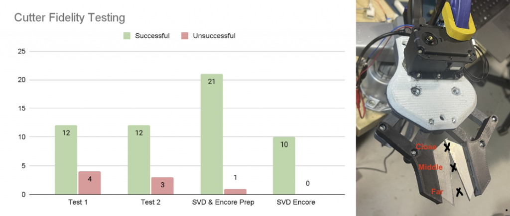
After the first initial tests (Test 1 & Test 2), we were still experiencing unreliability in cutting at the far position. In order to control for this issue, we made the jump from a gear ratio of 2 to 3, at which point we were able to successfully cut the peduncles at a rate of 97% across 32 cuts during SVD & Encore Prep, as well as the Encore demonstration. Note that this is the performance at the subsystem level, as we experienced some motor failures at the system-level demonstration.
Control Scheme
he software control methods were controlled using the DynamixelShield library, which was made possible by using the Dynamixel Shield by Robotis (below, right). This shield enables streamlined software development of the motors, as the associated library includes higher-level functionalities such as position control, factory reset, reading the encoder position, etc. During development, we discovered that the shield communicates with the Arduino via its RX/TX pins. This was an issue when considering integration with our system because we used rosserial as a medium for ROS communications. Rosserial, when operated over the standard USB type B, was inoperable as the port on the Arduino is also tied to the RX/TX pins. This causes the serial ports to be populated with two separate signals, and the Rosserial package cannot parse the packets.
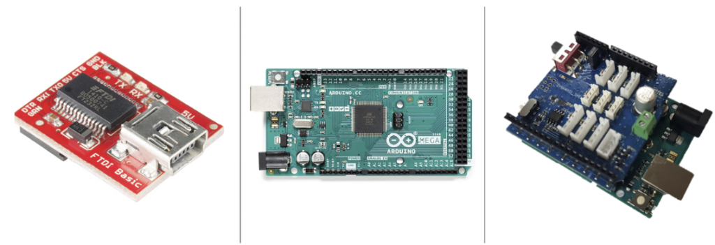
When discovering the conflict between the Dynamixel Shield and Rosserial, we operated with an Arduino Uno. To circumvent this issue, we transitioned to an Arduino Mega, which features three more hardware serial ports. After having extra availability of hardware pins, we were able to rewrite the Rosserial header files to augment the hardware pin to expect signals to be received over. This also required leveraging an FTDI chip (above, left) between the Arduino Mega and the central compute.
In its current form, the control scheme is relatively simple. The scheme uses the onboard PID controller embedded in the motor. The controller commands a position 10 degrees beyond a flush closure of the blades, such that when a peduncle is placed between the blades, a larger current is elicited. For the opening case, we used the closed-loop PID position control available on the motor hardware. Substantial effort was expended towards changing the default PID gains placed on the motor, in the hopes that a more aggressive maneuver would be generated. However, no noticeable change was observed. Both motors have an available firmware update that overhauls the communication protocols, making more advanced control methods available, such as torque control and position/current control. Moving forward, we anticipate updating the firmware and exploring these control protocols.
The current state of the controls and electronics are not robust at the system level, based on our current understanding, we believe there to be a hardware deficiency surrounding the electronics which caused the motor failure during our SVD. This will be addressed and resolved during the summer break to ensure that there is not a significant delay and other subsystems are not impeded.
Additional Components
In addition to the electronic components and end-effector components, there were additional mechanical components in order to complete the integration of our system.
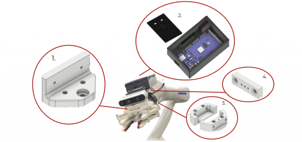
[1] Realsense D435i Mount
In mounting our Realsense to the top of the end-effector, we require a rigid connection between the two bodies. This ensures that once camera calibration is complete, no displacement between the frames can occur. We opted to create the mount such that the backside of the Realsense is flush along the extent of the front face of the camera mount, negating the potential for rotation of the camera.
[2] Electronics Housing
In order to mitigate the potential for loose connections and protect the components we created an electronics housing unit. This fixes in place the Arduino Mega, FTDI chip, and prototyping PCB board. By removing the potential for relative movement between components, we hope to reduce the risk of loose electrical connections. This housing also features openings for the USB type B port to allow seamless software updates to the Arduino, and also access to FTDI chip. The decision to create the electronics housing at the wrist of the Kinova arm was also influenced by the stability of serial communication. We have more faith in the stability of USB communication traveling over the length of the arm, which requires cords at least 10 feet in length, to TTL communication protocols. Thus we wanted to minimize the length of the USB wire and minimize the TTL length.
[3] End-Effector Mount
In order to rigidly connect the end-effector to the wrist of the Kinova, we generated a two-piece mount that is a form fit around the base of the end-effector. This mount is attached to the wrist via five M5 bolts and then two 70 mm M6 bolts are inserted along the length of the end-effector to connect both parts.
[4] Spacer Block
In order to avoid a physical overlap between the end-effector mount and the electronic housing, we also included a spacer block. This spacer block serves as an intermediate mechanical interface and it also increases the distance between the housing and the joints of the Kinova arm to ensure the safety of the electronic components.
Motion Planning Subsystem
Overview
The manipulation subsystem provides the connection between the perception and end-effector subsystems. This subsystem involves taking information from the perception computations to place the arm in optimal locations. This subsystem also ensures that the arm will avoid generated constraints to minimize plant damage. The Kinova Gen3, which is a six degree-of-freedom arm made available through the Tepper AI Makerspace, was used for manipulation. However, the final arm we plan to use will likely be the UFACTORY xArm6.
For planning, the Open Motion Planning Library (OMPL) within MoveIt was utilized. We specifically used the RRTConnect algorithm from OMPL. We decided to use MoveIt for planning purposes rather than the Kinova SDK because we wanted to develop an arm-agnostic planner due to our lack of access to a manipulation platform.
Hardware Transitions
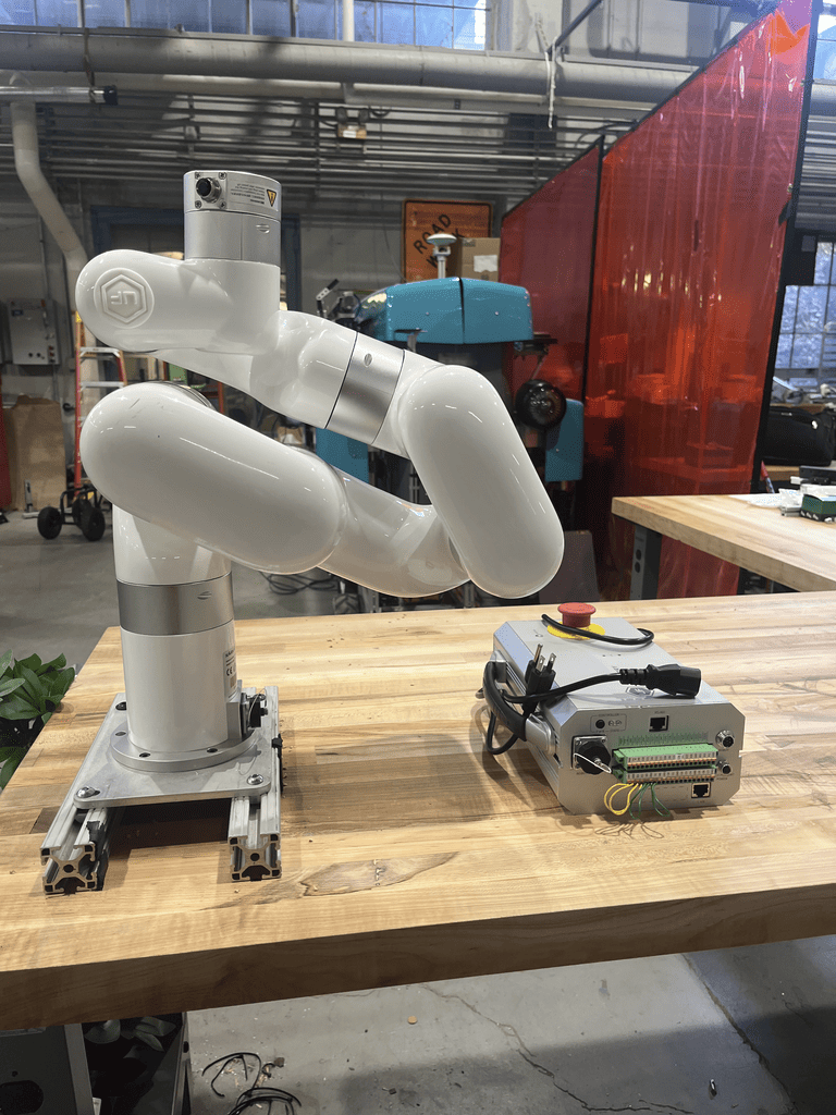
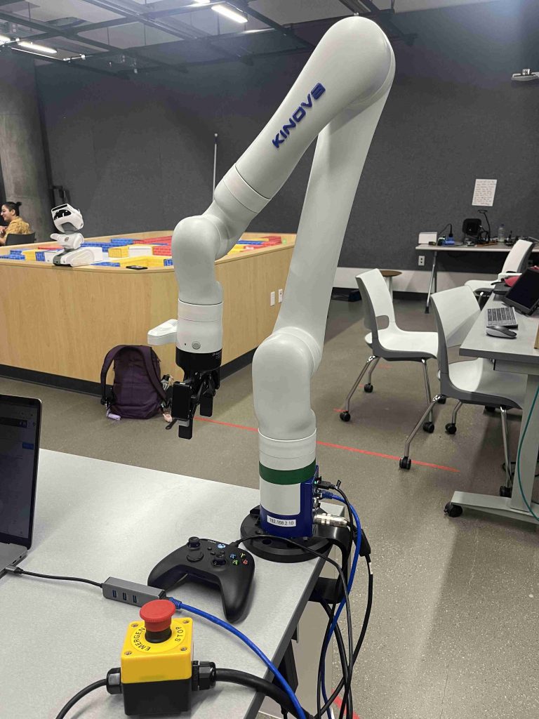
Initial development of this subsystem focused on development with the xArm as we anticipated using that arm for the SVD and Iowa testing. Below is an image of the xArm we were supposed to work with at our workbench in the high bay.
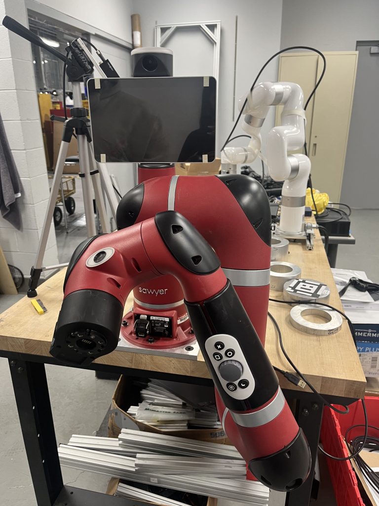
However, we discovered that the xArm was broken beyond repair, so we pivoted our focus towards development with the Sawyer robot for our SVD while also developing an “arm-agnostic” simulation for Iowa testing. Below is an image of the Sawyer arm which we pivoted to. We struggled with setting up the Sawyer arm, communicating with it over ROS, and moving it through MoveIt. We ended up having to switch to another available Sawyer arm, which was able to move over ROS.
After beginning testing with the Sawyer arm, we realized that it could not accurately generate trajectories for our orientation constraints and obstacles. We pivoted again to using the Kinova arm in the Tepper AI Makerspace. Below is an image of the Kinova arm in Tepper.
After finalizing which arm to use, we were able to complete testing on it to move it to desired positions while applying orientation constraints on the end-effector and defining peppers as obstacles to avoid damage to them.
Current Subsystem Status
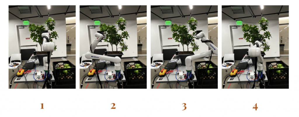
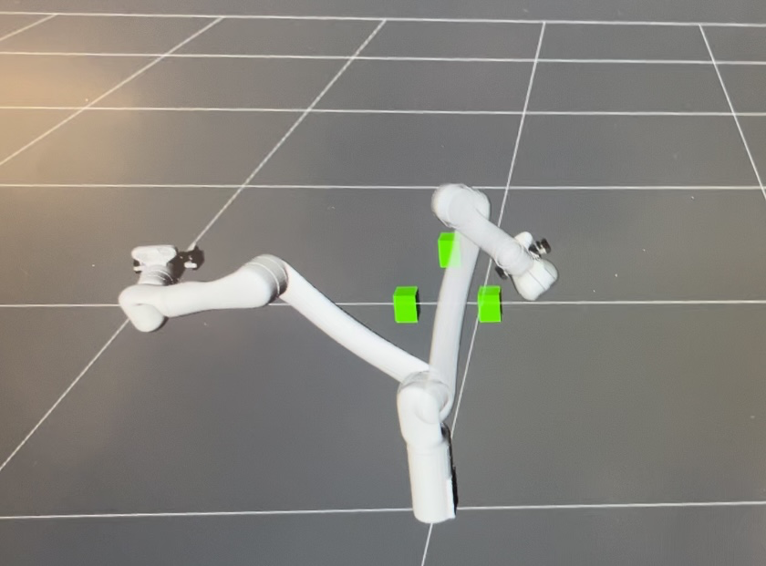
The arm goes through a series of maneuvers to successfully extract a pepper. First, the arm begins in a reset pose to ensure starting in a kinematically favorable configuration. Then, the arm approaches the plant to start detecting peppers. There are four predefined approach positions, as shown in the figure below. In our final system we aim to assign approach positions dynamically. The arm moves to the first approach position and detects peppers until peppers are no longer detected from that position. Then, the arm moves on to the next approach position and repeats the process to ensure that all peppers on the plant are detected and extracted.
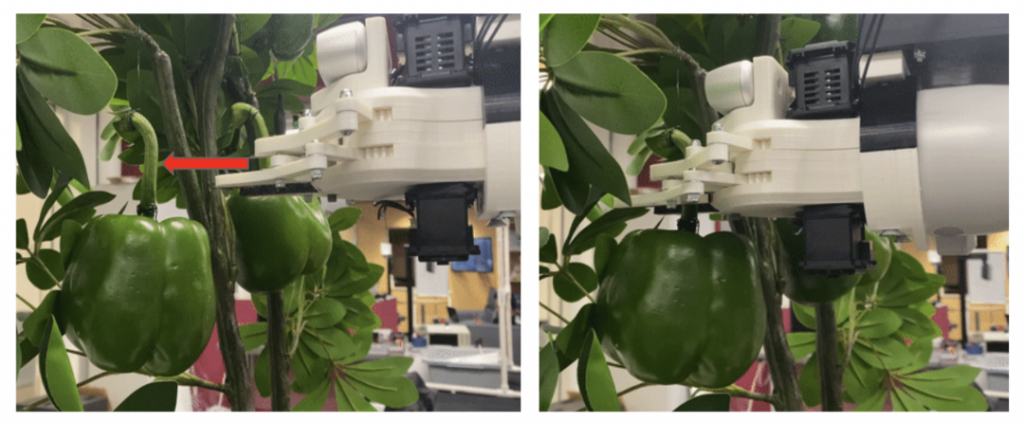
After moving to an approach position, the arm will execute multiframe moves. These are small movements which allow for multiple images with slight changes to be taken in order for the perception subsystem to filter out false positives and match peduncles with peppers. After the multiframe process is completed, the arm moves to an initial pre-grasp position. At this point, visual servoing begins on the perception side to determine any adjustments needed for the arm to move to a precise Point of Interaction (POI). After determining a more accurate POI, the arm moves to a secondary pre-grasp position which is aligned with the POI in two axes and 9cm back from the desired POI along the depth axis. Then, the arm executes a cartesian move along the depth axis to move to the POI. The figure below shows the arm in the secondary pre-grasp position and the arm after moving to the POI.
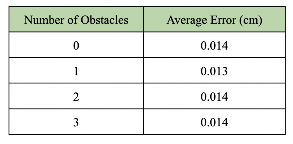
One of our performance requirements (PR.03.1) was to ensure that the end-effector position does not deviate from the planned trajectory by more than 1 cm. We were able to succeed in this performance requirement by accurately moving to the POI provided by the perception subsystem and following the planned trajectory throughout the move. Testing was also performed to validate this requirement. We chose randomized POI locations and added in obstacles. Then, we measured the difference between the desired and actual end-effector positions. The process was repeated for ten different desired poses for each set of obstacles. The results are shown in the table below. From the average error values, we can see that the deviation was much less than 1cm. Below the table is an image of the arm in simulation generating a trajectory to avoid obstacles.
After a pepper is extracted, the arm moves to the basket drop position to release the pepper. This movement allows us to meet our performance requirement PR.06.1: move the end-effector for pepper drop-off to within 15 cm above and within the radial bounds of a 50 cm diameter basket. All performance requirements for this subsystem have been met at the subsystem level. However, currently obstacle avoidance has not been integrated at the system level. Therefore, PR.02.01 has not been met yet by the fully integrated system.
Perception Subsystem
The perception subsystem encompasses five significant tasks: the detection of peppers and peduncles, calculation of the point of interaction on the peduncle, processing of multiple frames to clear out false positives and negatives, prioritizing of the order of picking peppers, and visual servoing.
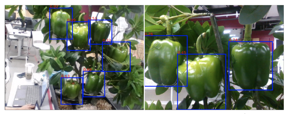
The detection of peppers and peduncles are done using YOLOv8, which outputs the bounding box or the segmented masks of the desired objects. The pepper detection network was trained on 5000 green bell pepper images to achieve a mAP50 of 0.98. The peduncle segmentation network was trained on 500 images of peduncles and achieved a mAP50 of 0.9.
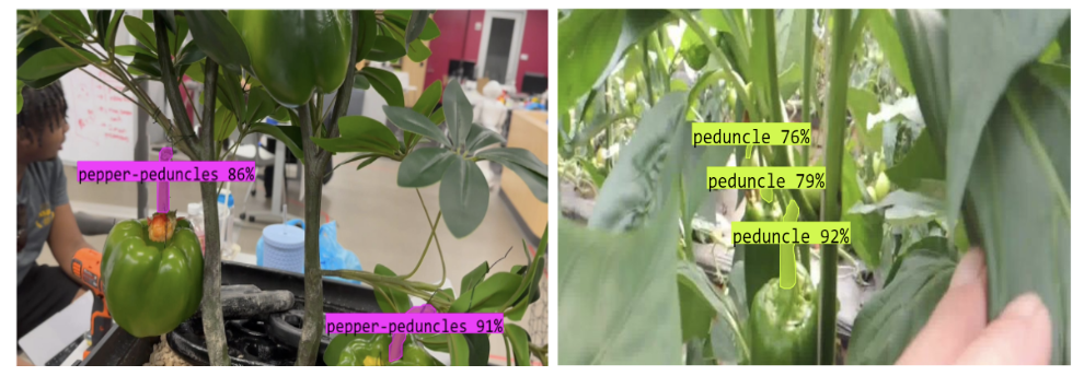
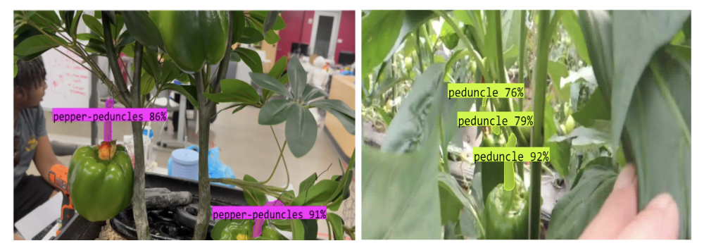
The network performance was tested on our SVD testbed. The long-range testing (camera is 1m offset from the peppers) achieved 75% accuracy, and the short-range testing (camera is 0.3m offset from the peppers) achieved 92% accuracy.
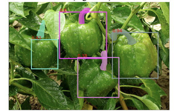
The pepper matching process was conducted in multiple steps. First, we retrieved all the pepper fruits and the peduncle locations. We calculated the distance between the pepper centroid and the peduncle for each pepper and found which peduncle was closest to the pepper. Once we had a potential match, we checked if the peduncle location made sense relative to the pepper location. Peduncles that were on the side/bottom of the pepper were filtered out. Once we ran this matching process multiple times for each pepper in the frame, we had a pepper match consisting of a pepper fruit and a pepper peduncle. The visualization below associates each pepper and peduncle match in the same color.
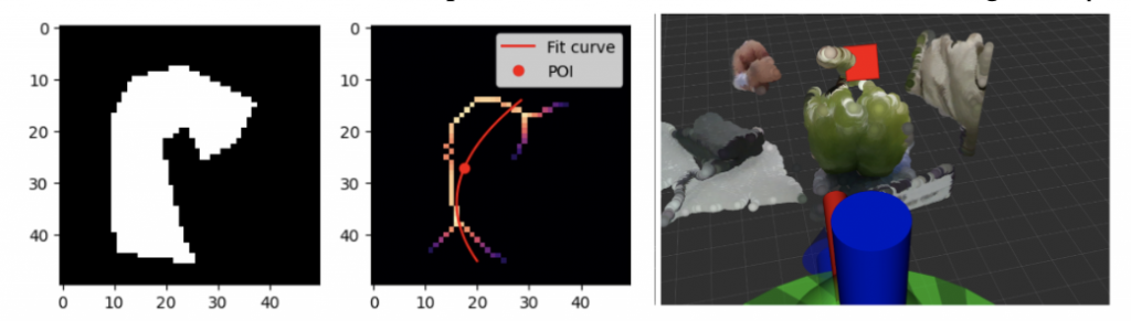
YOLOv8 provides the segmented peduncle’s boundary points, which is converted to a black and white mask as shown in the first plot in the figure below. The medial axis of the segmented mask is obtained with the help of the Python Skimage package and is shown in the second plot of the figure below by the colorful points. A parabolic curve is fit to the points on the medial axis. A least squares error between the points on the medial axis and the points on the fit curve is used as a metric to decide if the parabola is oriented vertically or horizontally. Subsequently, a point of interaction is calculated at a distance of half the total curve length from the top of the pepper fruit. This is a 2D point on the image, which is converted to a 3D point in space using the depth data provided by the RealSense camera. Lastly, the determined 3D point is verified by visualizing both the point cloud data of the environment and the point of interaction in RViz, as shown in the figure below.
When the perception subsystem has processed a single image, the system requests the arm to rotate its base joint by a small amount to get a different view of the plant. Multiple images of the plant with minor changes in the end-effector pose are obtained and processed individually to determine the pepper fruit detections and peduncle segmentations in each frame. The multi-frame algorithm takes every pair of frames and compares each pepper fruit in one frame with all other pepper fruits in the second frame to select the closest match. If a pepper fruit’s bounding box has an Intersection over Union (IOU) score above a specified threshold with another fruit’s bounding box in a separate frame, the two fruits are considered to be the same fruit captured in two different image frames. Hence, the two fruits are said to be associated with each other, and the number of occurrences of both fruits are incremented.
After updating the occurrences of each fruit in every frame and associating fruits across frames to each other, we classify fruit detection as a true positive if the fruit has been detected in at least 50% of the frames. The true positive fruits present in the most recent frame are matched to peduncles by the matching algorithm and are passed to the pepper ordering scheme. In case there are no true positive peppers (a matched fruit is a pepper) in the most recent frame, the multi-frame algorithm searches for them in the previous frame. The algorithm iteratively checks every frame by beginning from the most recent frame and ending at the first captured frame to ensure a true positive pepper is found. The purpose of the algorithm is to remove false positives and find false negatives that occur in a single frame.
Once the perception subsystem has determined true positive peppers after the multi-frame process, the peppers are prioritized based on a few heuristics to obtain a picking order. The final system will weigh depth, occlusion level, peduncle orientation, and distance from the arm. The current implementation of the system orders the peppers based only on the distance of the peppers from the arm. This is suitable because all our peppers are at a similar depth, have zero occlusion, and hang vertically downwards with a single orientation.
Reaching the POI relies on multiple sensors. The initial calculation of the 6D pose uses the RGBD camera, which is susceptible to some amount of noise. In addition, the position of the manipulator’s arm is read in using their encoders, which also introduces errors. Thus, directly going to the POI calculated in the multi-frame state often results in inaccurate end-effector positioning. To compensate for such errors, we use visual servoing once we get to the pre-grasp position. We rerun the peduncle segmentation network to obtain the point of interaction and align the POI to the center of the end effector, improving the reliability of the system.
Integration
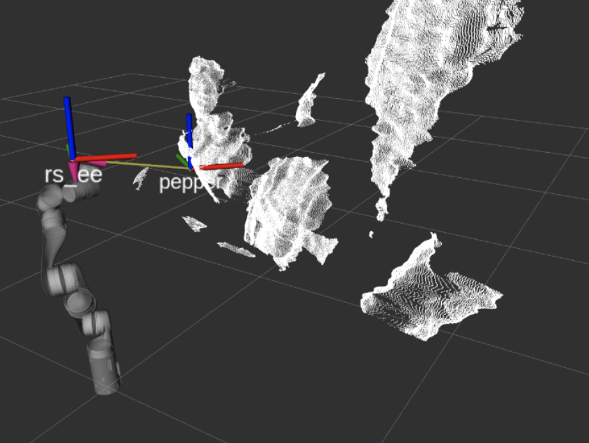
To integrate the perception and motion planning subsystems, we created a ROS pipeline to share peduncle POI and pepper obstacle information. We also created new ROS TF Frames to transform the RGBD camera info to the same reference frame as the arm. Below is an image of the point cloud and arm in RViz with the new TF frames shown.
Additionally, we created a mount to attach the end effector to the Kinova arm, along with housing for the arduino. The full end-effector with the mount is shown below.
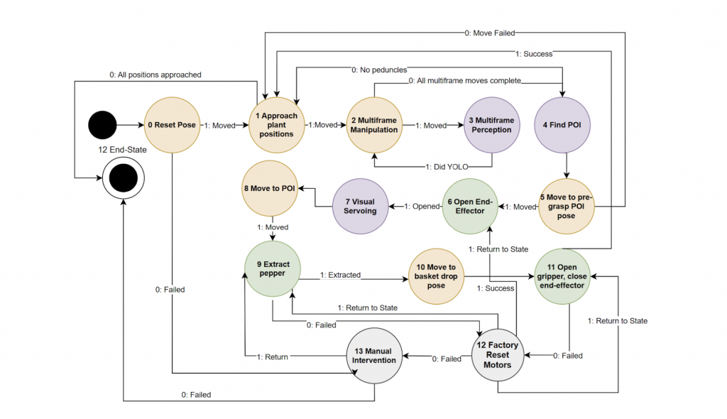
As part of the integration, we developed a system-level state machine and ROS pipeline. A diagram of the state machine is shown below.