Wiring Diagram
The team plans to build a LED PCB that can be installed around the sensor payload.
The PCB board contains two strings of 4 LEDs each: one string of white LEDs, and
one string of UV LEDs. The area surrounding the pipeline robot can be illuminated
well enough for cameras and sensors to function properly by adjusting the
brightness of these LEDs.
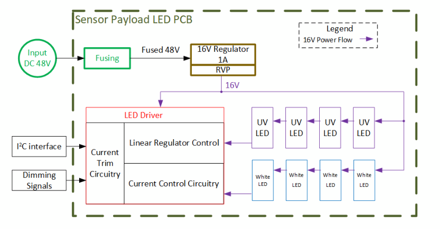
The PCB board mainly consists of two parts: the power regulation circuit and the
LED circuit. The board’s power source is connected via a female XT60 connector
and takes in a 48V input, which will be stepped down to 16V by the power regulation circuit and then used to operate the LED circuit.
The purpose of the LED circuit is to contain a programmable port so that the
computer can send out commands to the board to control the brightness of the
LEDs. Also, we need to make sure the circuit is stable, current protected, and reduce peaks as much as possible.
The white LEDs are for general illumination that will be used in our project. The UV
LEDs are for further repair purposes to detect luminescence material, which will not
be used in our current project. These will be used in the follow-on work of our
MRSD project.
The input source is a 48V DC power supply from the outside of the robot, connected via a female XT60 connector to the PCB board. Regulation is needed for
the board, which is from 48V to 16V for LED circuit operation.
The brightness of the LEDs will be adjusted by using “adjustable voltage pins”.
Analog voltages or PWM-generated voltages can be applied to the pins. The range
is 0V to 2.5V, and higher voltages will result in brighter lights.
The current for white LEDs is 350mA continuously and 1A in peak situations.
The current for UV LEDs can be less than 700mA continuously and 700mA in
peak situations. The 4 white LEDs and 4 UV LEDs are in series respectively.
The two series are in parallel.
Total continuous current for the LED circuit: 0.35 + 0.7 =
1.050A. Total current in peak situations: 1+ 0.7 = 1.7A.
Total power: 2.5 * 0.35 + 2.5 * 0.7 = 2.625w.
Regulator efficiency: ~16V/48V = 33.33%.
Regulator output voltage: 16V.
3 connectors in total for the whole PCB Board.
i. 1 connector for input XT60 connector for 48V/2~2.5V.
ii. 1 connector for white LED input Pin
iii. 1 connector for UV LED input Pin
The board will deal with reverse voltage by using diodes and deal with
over-voltage using specific components like TVS diodes etc. Also, capacitors will
be used to steady voltage.
For the board, we do not need to monitor the input voltage or output voltage, and we do not need any manual switch. But the LED circuit should be able to be controlled by the computer for brightness and on/off status. This could be realized by Arduino, but it could be better if the circuit can be directly controlled by computer commands such as I2C. This will be figured out later to see if the components fit the design.
The architecture is shown below and the design sketch is shown on the next page.
Board size :
Inner diameter : 4.6 inch
Outer diameter : 5.6 inch
Schematic Circuit Diagram
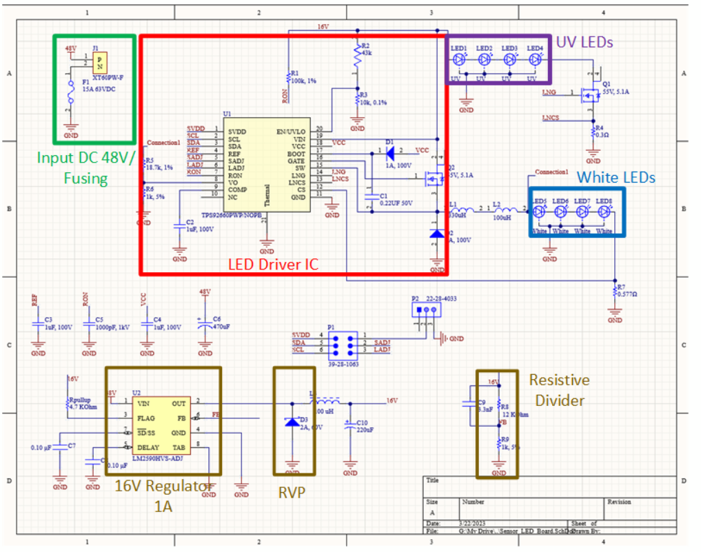
Voltage Regulators Analysis
As the current for white LEDs is 350mA continuously and 1A in peak situations, we found LM2590HV 150 kHz 1A Step-Down Voltage Regulator can fit our requirements.
We take its adjustable version which is LM2590HVS-ADJ and its output voltage range, 1.2V to 57V ± 4% max over line and load conditions. Also, it can guarantee 1A output load current.
Regulator efficiency: ~16V/48V = 33.33%
Regulator output voltage: 16V
Heat dissipation at nominal conditions: At 48V input, 16V 1A output, efficiency in the
typical case is rated at 76%.So to output 16W of power (1A*16V), we draw 21.05W
(16W/0.76). Losses are 5.05W.
Heat dissipation at peak conditions: In the datasheet, it doesn’t show any limit
efficiency.
Method to dissipate this heat: We will dissipate the heat through large ground planes.
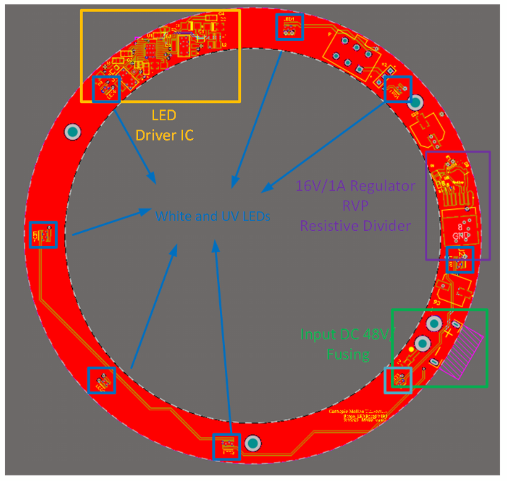
PCB Layout
There are three through holes on the LED ring which are connected with an
adapter. This adapter will also make RealSense mount on the robot. The XT60
connector will be placed in the upper position so that motor power 48V can
connect with it.
Datasheets
The datasheets which are pertinent to our team’s work have been linked below.
Two-String LED Driver – Texas Instruments
LM2590HV SIMPLE SWITCHER® Power Converter, Regulator – Texas Instruments
LED HIGH POWER C03 UV Product Series
Note: These datasheets are located in the team’s private storage space and will always be accessible by the team.