The following are the details of each subsystem
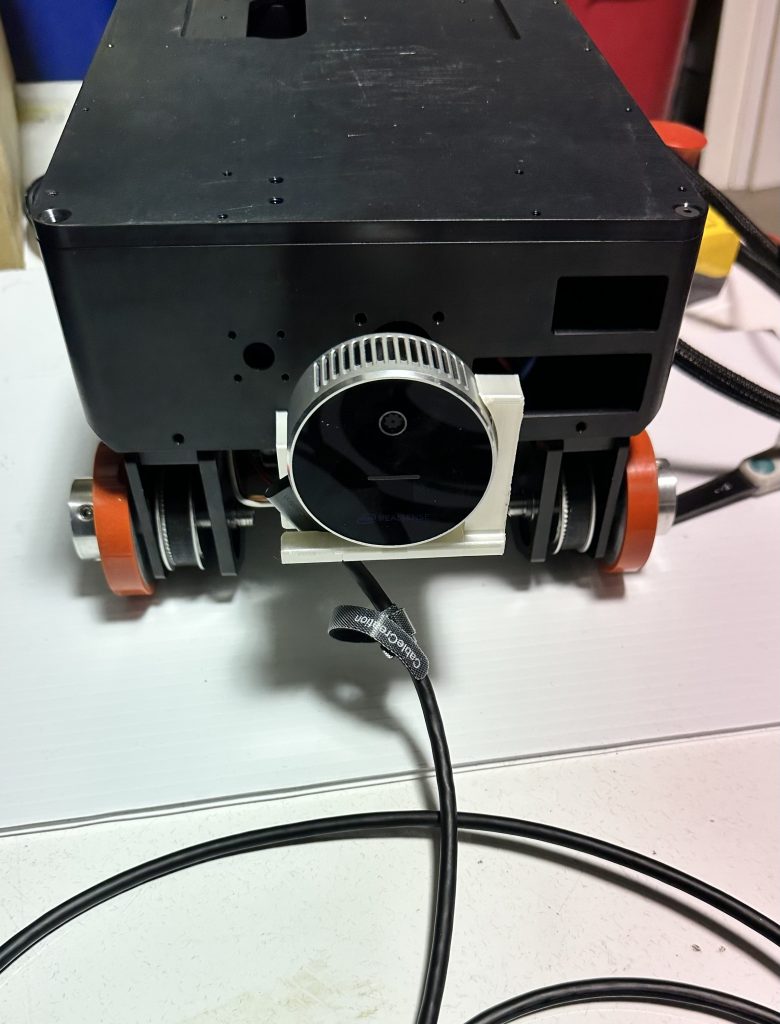
The robot built by the team is designed in a way such that it allows the robot to traverse inside a 12-inch pipe without any hindrances. The following figure shows the build of the robot hardware platform.
The following videos demonstrate the capability of the robot to traverse inside a 12-inch pipe.
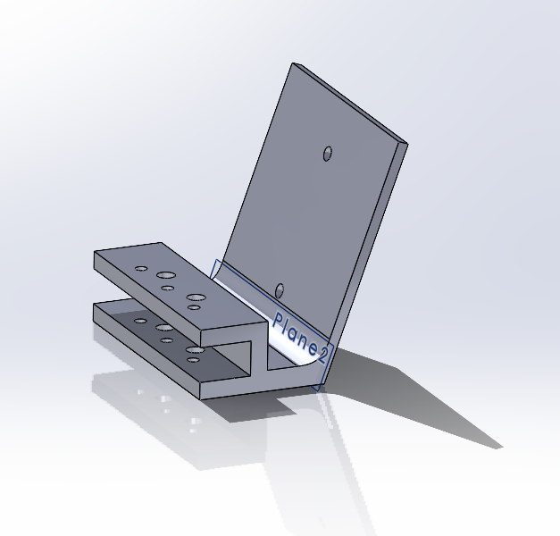
Sensor mounts were also designed and 3D-printed which were used to hold the Intel RealSense L515 camera. The following figures show the final designs of the sensor mount.
Before integrating each of our subsystems with the robot hardware platform, they are first tested in the simulation environment. The following video shows the work done in the simulation subsystem, where the simulation environment was built using Gazebo.
Color features and textures are present within the pipe and the robot with the Intel RealSense sensor plug-in is able to move inside the pipe.
Left – Raw RGB image data received from the sensor
Right – LIDAR data pointcloud returned from the sensor
Localization & Mapping Subsystem
For the purposes our project, we are trying to build a pointcloud map of the inner surface of the gas pipeline.
The following video shows the work done so far for this subsystem in the simulation environment where the output generated is a pointcloud mapping boundary of the pipe and obstacles.
In the perception subsystem, the obstacle detection algorithm was built to detect objects inside the pipe. The high-level goal of the perception subsystem is to be integrated with the planning & control subsystem and send the appropriate messages when an obstacle is detected inside the pipe. At present, the perception subsystem sends out messages of obstacles being detected when the sensor is within a distance of 30 cm from the object.
The following video shows the results of the perception subsystem built and the associated test results.
In this subsystem, initial work was to write instructions where the appropriate commands are taken from the user and sent to the HEBI motor drivers to make the robot wheels turn.
The following videos demonstrates the capability of the control subsystem.
Full System Development & Subsystem Integration
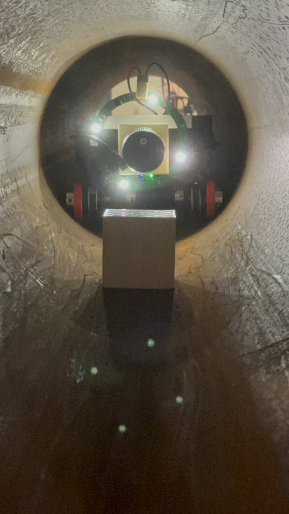
At present, the perception, planning and control subsystems have been integrated to the robot hardware platform. The robot is now able to take commands from the user and move inside a 12-inch straight pipe, look for obstacles inside and when detected, stop all movement inside the pipe.
The following video shows the tests conducted so far and the results obtained. In this video, a cube of ~9 cm in length x width x height is used as an obstacle inside the pipe and the robot is able to detect the obstacle and stop within a distance of 30 cm.