Overall System Design
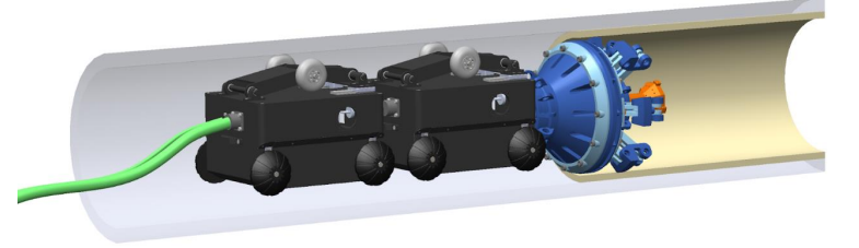
The figure above illustrates the robot traversing inside a pipe. For the purposes of our project, the team will be starting work with one module before moving on to multiple ones.
A detailed description of each of the subsystems of the robot is presented below.
1. Hardware Subsystem
The hardware subsystem is one of the most fundamental subsystems in the pipeline inspection project. Algorithms in a simulation are entirely different from the actual world operation. Although the project focuses more on algorithm development than mechanism design, a satisfying hardware platform should be stable, durable, and easy to maintain. The backup hardware platform could be Hebi’s Tready Jr or another version of the robot developed by the Biorobotics Lab.
The hardware platform is designed with modularity for ease of maintenance and multifunctional use. The main structure consists of the sensor payload and the driver module. The frame of the driver module is built as an empty box with two motors and four wheels. Inside the box, there will be enough space for onboard computing and a control board. An adjustable help wheel is located on the top of the driver module to squeeze the pipeline’s inner wall in case of slipping during movement and turning.
The sensor payload will be connected to the front of the driver module, and it does not have an actuator, as it is solely driven by the driver module. An adapter at the back of the driver module will enable it to connect to another identical driver module for greater power. For the mandatory project requirements, one driver module is sufficient. There is no battery in the robot due to safety considerations inside the pipeline. Instead, a power cable is connected to the rear-end of the driver module using a tethering mechanism.
2. Sensing Subsystem
The subsystem elements include the depth camera with IMU, a ring laser, basic processing for sensing data, calibration, mounting, and testing. For the sensing subsystem, we decided to use the RealSense D435i from Intel, which was our first choice based on the trade study, as the most critical sensor. The depth camera D435i combines robust depth sensing capabilities with the addition of an inertial measurement unit (IMU). It has great performance for object detection and is also suitable for the feature-sparse environment and 12-inch-wide pipe measurements.
In the RealSense D435i, the RGBD camera collects visual condition data for depth calculation and object detection from 0.3m to 3m. The IMU is used for robot pose estimation by collecting acceleration and angular velocity data. We chose model D435i from different types of RealSense sensors because it contains an IMU to help the robot better localize itself, considering the featureless inner pipeline environment that would limit the performance of visual data analysis. A ring laser is included in the sensing subsystem to measure position and boundary conditions, which is used to enhance performance to achieve the accuracy stated in the performance requirements section. We may also use another camera to record the video data as output, as mentioned in the cyberphysical architecture part.
If the performance of the RealSense sensor in testing does not meet requirements, a fallback for the sensing system is that our team could change to the ARPA-E sensor payload. The payload, designed by the Biorobotics lab, has relatively high-quality performance for the pipeline environment aimed to create very dense point clouds. For the payload, our team also has the flexibility to change the model and type of a specific sensor on it. However, in this case, our team needs to spend much more time learning and integrating the payload into the whole system, as it’s still a research product with little documentation.
3. Perception, Localization & Mapping Subsystem
The Perception, Localization, and Mapping subsystem is the most critical subsystem in this project, as it serves as the foundation for the autonomy objective. This subsystem will run on ROS2 and be visualized in Rviz.
The perception algorithm is essential in linking the sensing subsystem and the whole software subsystem. The main tasks under perception will be processing data, filtering noise, frame transformation, and computing depth, as demonstrated in the cyber-physical architecture. The perception subsystem performs 3D object detection and RGB visual inspection, which allow the robot to detect pipeline boundaries and large obstacles.
As the system operates on a short, straight pipeline, encoders in motors and the tether are good enough to measure position along the pipe. The key position the subsystem requires is the relative distance from the entrance. The system also requires pose in the yaw axis for further mapping, which necessitates IMU data to estimate the pose.
The mapping will combine environment information and localization into a 3D point cloud model using tools like Voxblox. The output dense point cloud will visualize colored detail in Rviz as one of the system’s outputs.
4. Planning & Control Subsystem
The planning and control subsystem aims to move the robot through the pipeline smoothly without hitting the boundary or any obstacles. The planner will take information from the mapping result and dynamically plan the local path by finding desired waypoints and generating a trajectory. The planner will also plan the velocity and acceleration to make the movement smooth without sudden stops. In the particular case of a sizable positive obstacle being detected, the planner should stop the exploration according to mandatory requirements. For desired requirements, the planner shall change the robot’s pose and maneuver around the obstacle.
As described in the hardware subsystem, the robot is driven by two motors and four wheels. The controller will control the two motors using the PID controller in both position and velocity using control input from the planner. The PID controller is a simple but robust choice for simple movement. Another option for position control may be a pure pursuit controller.
5. Simulation Subsystem
The simulation subsystem will be a low-cost tool and provide the team the opportunity to conduct more experiments. The goal of the software simulation subsystem is to model the pipeline’s autonomous traversal function when the hardware is still under development and evaluate the performance of all software algorithms. The simulation subsystem is broken down into environment modeling, robot modeling, the establishment of a ROS2 interface, and result visualization.
Gazebo is a built-in software application in the Linux operating system that contains abundant existing popular 3D models for robotics. Gazebo also allows user-defined models and environments. For environment modeling and robot modeling, Gazebo is a powerful tool. Also, it has a strong interface with ROS, which allows the simulator to demonstrate the software outputs. Rviz is also a simulation tool with stable ROS interfaces and will be helpful in the visualization of the robot’s state, trajectory, depth information, and returned point cloud. Rviz supports displaying videos and showing 3D models as well.
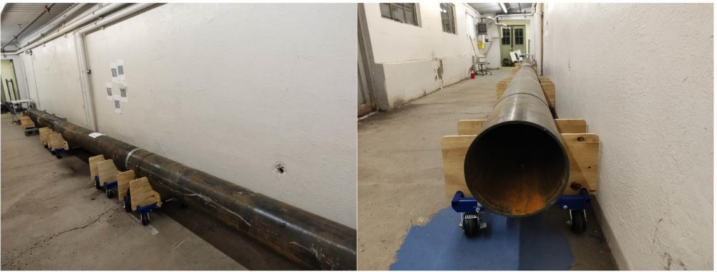
Test Site
The selected test site has already been built in the Field Robotics Center (High Bay) at CMU’s Robotics Institute, as shown in the figure below. The test site is an actual gas pipeline with rust and other defects inside. The test site’s inner diameter is 12 inches, and it is 9 meters long, which can be divided into three 3-meter sections. This test bed is sufficient for integration and testing of our mandatory requirements. Another test site option is the pipeline network of People Gas Company in Pittsburgh.