Mandatory Performance Requirements
| ID | Functional Requirement | Performance Requirement |
|---|---|---|
| M.P.1 | Localize Itself | The drone shall localize itself at least at 10Hz |
| M.P.2 | Localize Itself | Localize itself within a drift of 4% |
| M.P.3 | Be Capable of Completing Mission | Have flight time of more than 10 minutes |
| M.P.4 | Plan Safe Trajectory Towards Goal | Navigate trees with separation of at least 5m |
| M.P.5 | Communicate with User | Have a Communications Range up to 150m |
| M.P.6 | Detect Fire, Localize Fire | Detect fires with an accuracy of more than 70% |
Non-Mandatory Performance Requirements
| ID | Non – Functional Requirement |
|---|---|
| M.N.1 | Have appropriate dimensions/size |
| M.N.2 | Have failsafe and redundancies |
| M.N.3 | Be of Rugged Design |
| M.N.4 | Rely on Passive Sensors Only |
| M.N.5 | Be Easy to Use |
Desirable Requirements
| ID | Functional Requirement | Performance Requirement |
|---|---|---|
| D.P.1 | Plan Safe Trajectory Towards Goal | Navigate autonomously between trees at minimum 1m/s |
| D.P.2 | Detect Fire and Localize Fire | Localize the Fire within 5m |
| D.P.3 | Operate in GPS degraded forest environment | Localize itself in GPS degraded environment with less than 0.05Hz of GPS connectivity |
Desirable Non Functional Requirements
| ID | Functional Requirement |
|---|---|
| D.N.1 | Be FAA Compliant |
Functional Architecture
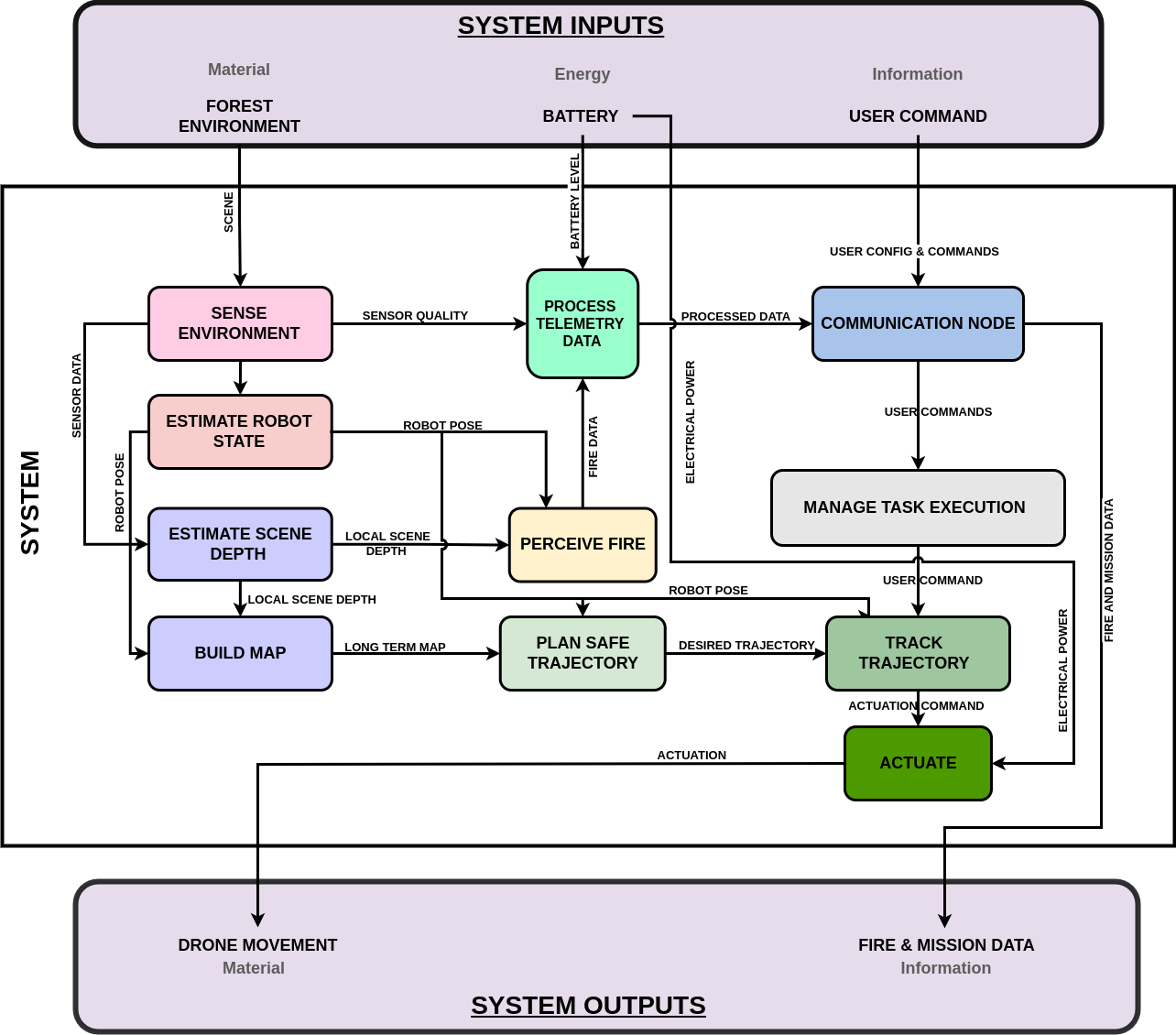
The inputs to the system are categorized broadly into Material/Mechanical input, energy into the system, and information input. The material input for our system is the wildfire environment the drone is traversing which is perceived by the on-board sensor suite. The electrical energy from the battery is utilized by the computation, communication, and actuation modules mounted on the drone’s airframe. The only information input to the system is the GPS location of the estimated wildfire location. The system transmits mainly three data outputs, fire heat map, wildfire primary hotspot location, and the drone’s telemetry data. Summing up, the system takes the GPS coordinates of the rough estimate of wildfire location and transmits the fire heatmap, primary hotspot location, and telemetry data.
Cyber-Physical Architecture
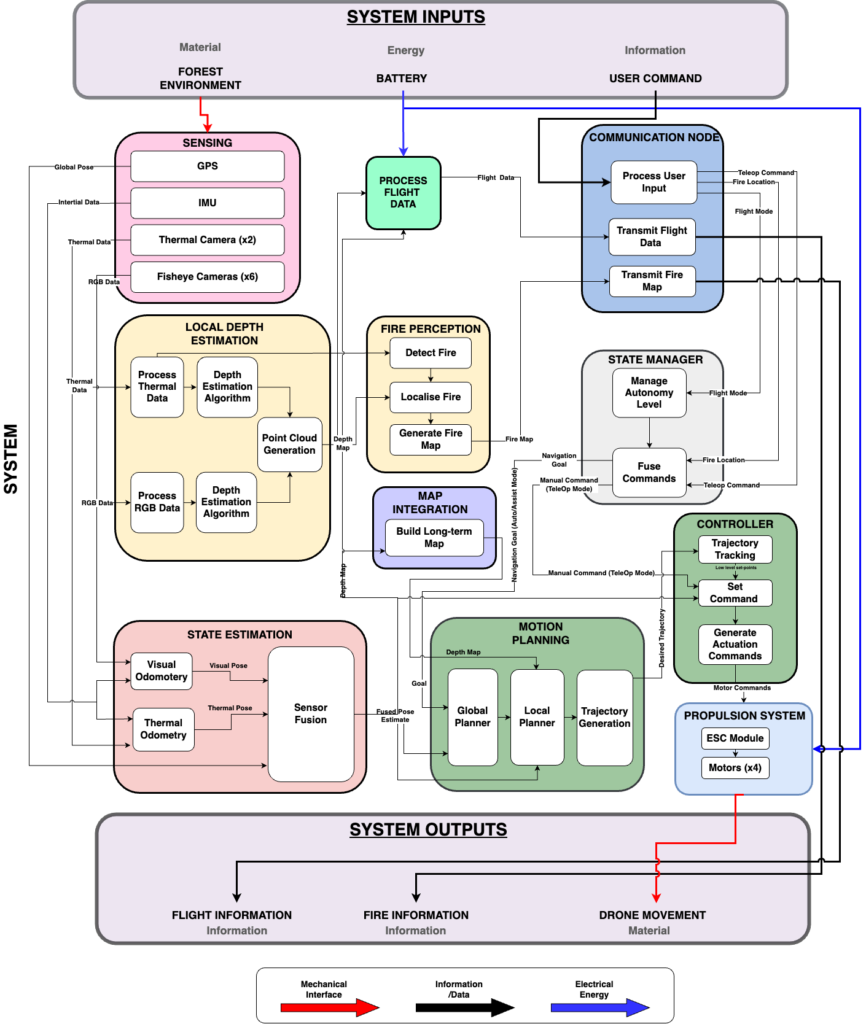
The inputs to the system are the environment (material), electrical energy from the battery, and the user command (information). The desired output of the system is drone movement and fire information. The major subsystems present are Sensing, Depth Estimation, Fire Perception, Map Integration, State Estimation, Motion Planning, State Manager, Controller, Propulsion System, and Communication Node.
The flow of information between the modules is as follows. The sensor suite present on the aerial platform senses the environment and transmits the RGB and thermal image data to Depth Estimation and State Estimation modules. The State Estimation module takes in GPS location (degraded), thermal images, and RGB images and provides an accurate position of the robot. The local depth map is transmitted to the fire perception module for generating a heat map of fire locations, and to the Map Integration module. The output of the Map Integration module is a long-term global map that is used for motion planning. The planned trajectory is tracked using the Control and Propulsion subsystems. These are described in more detail in the subsystem descriptions.
Subsystem Descriptions
1. Aerial Platform
This subsystem comprises the entire physical robotic system. It consists of all the components and assemblies required for the final system deployment and validation.
Structural Airframe: Acts as the central base platform on which all other sub-systems are integrated. Based on our requirement for endurance and size restriction, we have conducted a trade study to decide on the propulsion system. Through the trade study shown in Figure 10.1.3 in Appendix 10.1.3, we have decided on using 15.5-inch propellers with quadcopter configuration. The airframe will be selected off-the-shelf based on these considerations.
Propulsion Drive: The critical component in our system that enables seamless and efficient flight. Based on the trade study shown in Figure 10.1.3 in Appendix 10.1.3, we have decided on using four KDE4215XF-465 BLDC motors for propulsion, coupled with 15.5” x 5.3” Bi-Blade CF propellers.
Sensor Suite: Comprises of all the sensors required to perform autonomous navigation as well as fire detection/mapping. Our sensor suite consists of IMU for odometry, GPS for state estimation (although the estimate is noisy due to degraded GPS), 6 fish-eye cameras for generating the local depth map, and 2 thermal cameras for both local depth map and fire perception.
Low-level Autopilot: An MCU is required for tracking the generated commands and setpoints from our higher-level autonomy stack.
On-Board Mission Computer: The primary compute unit of our robotic system which will house all our autonomy and fire perception stacks.
Power Delivery: Required to ensure adequate power supply to all the other sub-systems. The selected motors require a 6S 10000 mAh Li-Po Battery.
2. Fire Perception
The fire perception pipeline involves major subsystems derived from the thermal camerasensing capabilities. These are fire mapping and fire localization. The ORDv3 aerial platform is currently equipped with 6 fisheye cameras for a 360-degree field-of-view and 2 front-facing thermal cameras. This enables dense environment mapping, but only sparse thermal capabilities. This makes the fire perception module of utmost importance. The fire mapping is done using FLIR Boson thermal imaging cameras, which are highresolution precise sensors that will help us detect primary and potentially secondary hotspots. The aim is to explore both classical approaches (such as thresholding, clustering, etc.) and learning-based approaches (such as semantic segmentation, hotspot prediction, etc.) to perform initially binary classification of a discretized space, and extend this to intensity mapping of the
fire. The fire localization module makes use of the thermal and RGB depth estimation subsystems to project the detected hotspots onto the sub-canopy terrain. This potentially gives us a 2.5D map of the environment, which along with our mapping pipeline, is capable of transmitting real-time feed to the ground control station, in the form of a local map of the environment. Possible extensions to this include providing navigation feedback to the firefighters to combat previously mentioned entrapment issues.
3. State Estimation
State Estimation module takes in GPS location (degraded), thermal images, and RGB images. It performs Odometry using both the image data essentially giving the robot pose. The estimated pose and the GPS are fused to provide an accurate position of the robot. The output is utilized for motion planning, map integration, and telemetry modules.
4. Depth Estimation
As per the mandatory non-functional requirement M.N.4, we are required to use only passive sensors, which inhibits us from using LiDAR. Therefore to obtain an occupancy map, we require a depth estimation of the obstacles. This is achieved using this subsystem. The inputs to the module are thermal images from the two thermal cameras, essentially acting as thermal stereo and RGB images from the 6 fish-eye cameras. These 6 fish-eye cameras act as 6 stereo pairs, 3 pairs for the top view and the other 3 pairs for the bottom view. The two depth maps generated are fused to obtain the local depth map which is transmitted to fire perception, map integration, and telemetry modules.
5. Mapping
5.1 Long-term Occupancy Mapping
The mapping sub-system takes in the raw instantaneous 3D point cloud from our depth estimation module along with the fused pose estimate of the robot to build a long-term dense 3D occupancy map, which will be used by the global planner in our motion planning system to compute safe collision-free paths to the desired goal pose.
5.2 Local SDF Mapping
In addition to the long-term 3D occupancy map, we will also maintain a local 3D signeddistance field (SDF) map centered around the robot which will be used by our optimisationbased local planner to generate safe and feasible trajectories. This map will be generated from the binary occupancy map generated above.
6. State Manager
Although our drone will be autonomous, the dangerous elements of our operational environment require our system to have an assistive teleop mode as a fall-back for the safety of firefighters and the drone in case of primary autonomy system failure. The state manager module is a FSM-based manager which also sets the level of autonomy of our system. It takes into account the flight mode set by the user and the estimated fire location which we receive from high-altitude sources, and fuses them into an output mode. This is the mode that our controller follows.
7. Motion Planning
The motion planning sub-system is formulated as a hierarchical framework consisting of:
Global Planner: This forms the highest level of the motion planning stack which plans a safe global route in the form of 3D position waypoints to the desired goal given the occupancy map and the drone’s current state estimate.
Local Planner: Given the generated global plan from the global planner and the local 3D SDF map of the environment and current pose of the drone, the local planner is then responsible for generating high-quality locally optimal trajectories taking into account the kino-dynamic constraints, safety constraints, etc.
Reactive Planner:
This planner is an independent unit that is utilized only when the vehicle is in assistive autonomy mode or reactive navigation mode. Unlike the above two planners, this planner takes the real-time 3D depth point cloud from the depth estimation module. The reasoning behind this choice is to alleviate any problems arising from mapping artifacts introduced due to the drift in our state estimation module. Though this planner would be globally sub-optimal, we will be guaranteed to have locally optimal performance which is critical for the safety and recoverability of the system. Just like the local planner, this planner outputs safe and feasible trajectories.
8. Controller
After the motion planning sub-module generates an optimal trajectory for navigating through the cluttered environment, the controller/trajectory tracking sub-system is responsible for translating these high-level reference trajectories to low-level flat set-points (thrust+attitude) commands, which are then sent to the FCU for low-level control and stabilization. The behavior of the controller will be defined by the state manager as per the operational mode commanded by the user.
9. Communication Node
The communication subsystem is tasked with multiple responsibilities. Initially, it handles the processing of user commands, transmitting crucial flight information, flight mode (assistive-teleop mode and fully autonomous mode), and teleoperation commands to the State Manager subsystem. The utilization of the teleoperation command is contingent on the flight mode being manual. Additionally, the subsystem is responsible for transmitting both the fire map and flight metadata information to the Ground Control Station.