Maximum Speed: between 3 to 5 mph Range:10 miles on a single charge
M.N.4
Modularity
Modular design for easy maintenance
M.N.5
Affordability
Cost-efficient, priced at 150-200% of standard non-autonomous wheelchairs
M.N.6
User Interface
Generate wheelchair traversable path
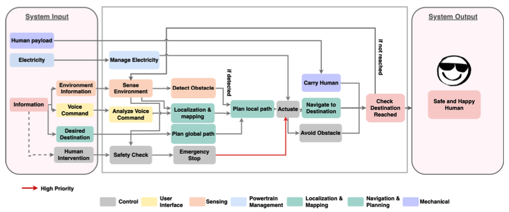
Functional Architecture
Cyberphysical Architecture
System design description
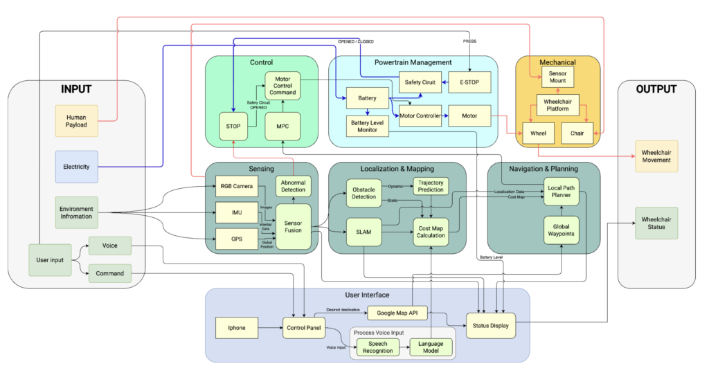
The full cyber-physical architecture is illustrated in Figure 6.1. This architecture is derived from the functional design and is segmented into various blocks, each representing distinct functionalities. The lines connecting these blocks indicate their interconnections, with red lines denoting mechanical connections, blue lines for electrical connections, and black lines for data transmission. The entire system is organized into seven primary blocks:
User interface: This block facilitates user interaction with the system. Users can input their desired destination or voice commands through devices like an iPhone or a console. The system employs the Google Maps API to determine the global path from point A to B. Additionally, it utilizes the iPhone’s computational capabilities for speech processing, thereby enhancing user perception.
Sensing: This block utilizes RGB-D cameras, an IMU, and GPS to gather environmental data. The collected data undergoes sensor fusion before being forwarded to the localization and mapping block. Moreover, this block includes a component for detecting abnormal system behavior, which can trigger the STOP component in the control block if necessary.
Localization and mapping: The processed data from the sensing block is directed to two components. The mapping component performs real-time environmental mapping to generate a cost map, while the obstacle detection component identifies obstacles and updates the cost map accordingly.
Navigation and planning: Utilizing the cost map from the previous block, the local planner integrates the cost map with global waypoints from the Google Maps API. This allows the wheelchair to adhere to the planned global path while managing local obstacles.
Control: In this block, the Model Predictive Control (MPC) component uses the local waypoints generated by the navigation and planning block to produce motor control commands. A separate STOP component can override the MPC to issue an immediate stop command when activated.
Powertrain management: This block comprises the battery, motor, and motor controller, enabling the motor to propel the system. Emergency stops are linked to the safety circuit; if an E-STOP is pressed by the user, the safety circuit opens, activating the STOP component in the control block to halt the wheelchair immediately.
Mechanical: This block features a robust wheelchair platform that includes stable mounts for sensors, a user chair, and durable wheels for mobility.