Development Milestones
Report Date: May 3, 2025
1. Development Milestones & Evolution
- Milestone 1: Conceptual Architecture (November 2024)
- Initial design focused on a standard robotics pipeline: Sensing -> SLAM/Localization -> Planning -> Tracking -> Actuation/Control.
- Core triage-specific logic (Patient Detection, Pose/Vital Signs Estimation) and auxiliary modules (GCS Comms, Logging, Health Monitoring) were identified.
- This conceptual foundation aligned well with the principles guiding the final system architecture.
- Initial Consideration: SLAM/Localization was initially deemed important but may have been de-prioritized or addressed implicitly through GPS and onboard sensors in the current iteration.
- Milestone 2: Grounding in Reality – Adopting AirStack Components (December 2024)
- Recognizing the complexity, the Airlab AirStack framework was evaluated as a potential foundation.
- Key Adoption: The functional AirStack MAVROS Interface (ROS 2) for PX4/MAVLink communication was adopted. This provided a robust hardware interface layer, simplifying actuation and control tasks.
- Initial Behavior Framework: AirStack’s Behavior Tree (BT) concepts and node were reviewed, providing a structured approach for planning and task execution managed via GCS commands. Note: While initially considering AirStack’s BT framework, development later shifted towards a custom behavior management system (see Section 2.2.1).
- Milestone 3: Containerization, Integration, and Semi-Autonomy (January – February 2025)
- Focus: Making software components deployable and integrated.
- Dockerization: Began containerizing AirStack components and custom code into the target Docker architecture (Robot Container, Detection Container).
- Key tasks included dependency resolution, configuring ROS 2 within containers, and setting up networking.
- Challenge: First-time Docker build on the arm64 platform (NVIDIA Jetson) and configuring Fast DDS middleware posed significant hurdles.
- Integration & Debugging: Significant effort was invested in understanding adapted AirStack components (particularly launch files and middleware configuration), connecting them to basic GCS stubs, and resolving runtime issues.
- Achievement: Reliable semi-autonomous flight was achieved. The system could execute high-level GCS commands (Takeoff, GoTo Waypoint, Land) via the Robot Container interacting with MAVROS.
2. Current System Architecture (As of May 2025)
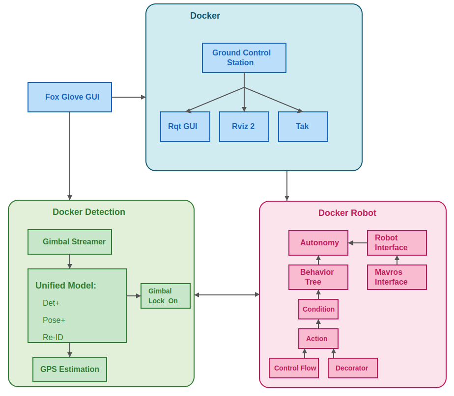
The software is now split between a ground station for human control/monitoring and the drone’s onboard computers, which handle flight, perception, and decision-making.
- Distributed System: Functionality is divided between the Ground Control Station (GCS) and the drone itself.
- Modular Onboard Software: The drone’s intelligence runs in two main Docker containers on its onboard computer (NVIDIA Jetson):
- Robot Container: Manages autonomous flight, navigation, and high-level decision making.
- Detection Container: Handles visual perception (seeing and understanding the environment) and controls the camera gimbal.
- Containerization (Docker): Using Docker ensures that each software component runs in its own isolated, consistent environment. This simplifies deployment and prevents software conflicts.
Ground Control Station (GCS)
This provides the operator interface to monitor the drone’s status, view its camera feed, and send high-level commands.
- User Interface: Built using Fox Glove, a web-based visualization tool well-suited for robotics data.
- Communication Core: Uses ROS 2 (Robot Operating System 2) for robust communication between the GCS and the drone.
- Data Flow:
- Uplink (Commands to Drone): Operator actions in Fox Glove (e.g., “Start Mission”) are translated into ROS 2 messages (services/actions) sent over the network to the Robot Container’s command interface (
/behavior_tree_commands). - Downlink (Data from Drone):
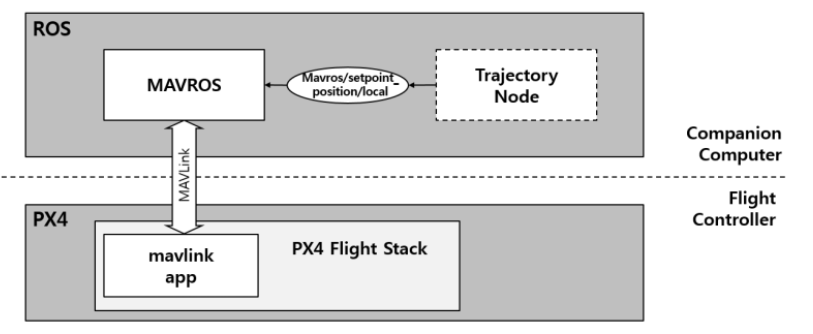
- Telemetry: Flight data (position, altitude, battery, etc.) comes from the drone’s flight controller (e.g., Pixhawk) via the MAVLink protocol. MAVROS (a ROS package) translates this into ROS 2 topics that Fox Glove displays.
- Video: Live video from the drone’s camera is streamed using GStreamer pipelines and displayed in the Fox Glove UI.
- Uplink (Commands to Drone): Operator actions in Fox Glove (e.g., “Start Mission”) are translated into ROS 2 messages (services/actions) sent over the network to the Robot Container’s command interface (
Onboard Software: The Drone’s Brain
The onboard intelligence is split across two Docker containers for modularity.
1. Robot Container
Executes autonomous missions, manages flight stability, and makes high-level decisions based on commands and sensor data.
- Built on an NVIDIA L4T (Linux for Tegra) base Docker image for Jetson compatibility.
- Uses ROS 2 Humble as the primary middleware.
- Includes key robotics packages: MAVROS (for Pixhawk communication), tf2 (for managing coordinate systems), and libraries like OpenCV, Python (NumPy, SciPy).
- Configured with development/debugging tools and SSH access.
Layer 1: Hardware Interface (mavros_interface)
- Purpose: Acts as the bridge between the ROS 2 software commands and the drone’s flight controller (Pixhawk).
- How: Uses a plugin (
mavros_interface) running within a ROS 2 node (robot_interface_node). It subscribes to internal ROS 2 commands (like desired velocity or position) and translates them into MAVLink messages sent via MAVROS. It also translates MAVLink status messages (like armed state, current mode) back into ROS 2 topics.
Layer 2: Behavior Management (BehaviorExecutive)
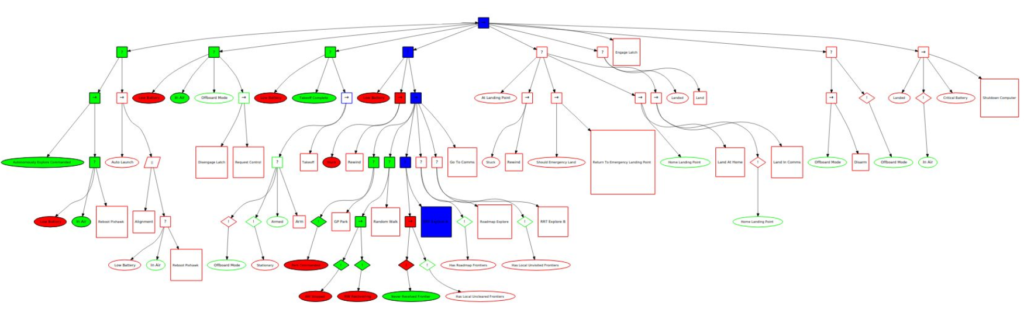
- Purpose: Orchestrates the drone’s high-level actions and sequences (the “what to do”).
- How: Implements a custom, event-driven system (managed by the
BehaviorExecutiveROS 2 node) rather than a standard Behavior Tree library.- Triggers (
bt::Condition): Listens for external commands (from GCS via/behavior_tree_commands) or internal state changes (e.g.,/mavros/state). - Actions (
bt::Action): Pre-defined code blocks for specific behaviors (e.g.,AutoTakeoff,GoToPosition,GeofenceMapping). - Execution Loop: A timer periodically checks if any Condition has been met to activate a new Action. When activated, the Action’s code executes, typically making calls to MAVROS services (e.g., set mode, arm, push mission waypoints) via the Hardware Interface Layer. Complex sequences (like search patterns) are managed by custom logic within specific Action implementations.
- Triggers (
2. Detection Container: Perception & Gimbal Control
Processes camera data to understand the environment, identifies targets (people), estimates their location, and directs the camera gimbal. Another Docker container with ROS 2, vision libraries (OpenCV, vision_msgs), and Python.
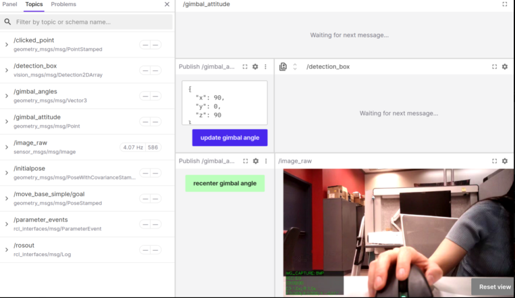
inted_gimbal Node (Perception Core)
- Video Input: Connects to the Gremsy gimbal camera stream via RTSP (using ffmpeg).
- Object Detection: Uses a YOLO model (
yolo.py) to detect persons in the video frames. - GPS Estimation: Calculates the estimated GPS coordinates of detected persons using the detection bounding box, drone’s GPS/altitude/heading (from MAVROS), and camera parameters. Keeps track of unique targets.
- Outputs (ROS 2 Topics): Publishes the processed video (
/image_raw), detection results (/detection_box), and estimated target GPS coordinates (/detection/gps_target,/target_gps_list).
payload_node Node (Gimbal Control & Tracking)
- Purpose: Controls the physical orientation (pan/tilt) of the camera gimbal.
- State Machine: Operates in different modes (e.g.,
MAPPING– point down,MANUAL_CONTROL,LOCK_ON– track target,SPIN– search pattern). - Visual Servoing (
LOCK_ONstate): This is the key tracking logic.- It subscribes to
/detection_boxfrom theinted_gimbalnode. - When a person is detected, it calculates the required gimbal angle adjustments (
track.py) to keep the person centered in the frame. - It publishes these adjustments to the gimbal via the
/gimbal_anglestopic, creating a closed feedback loop.
- It subscribes to
How the Subsystems Interact
The modular design allows for coordinated operation:
- Mission Start: The operator uses the GCS to send a command (e.g., “Start Search Pattern”).
- Command Reception: The command arrives at the Robot Container’s
BehaviorExecutive. - Execution: The
BehaviorExecutiveactivates the appropriate Action (e.g.,GeofenceMapping), which sends waypoints or velocity commands through themavros_interfaceto the flight controller. - Perception: While flying, the Detection Container’s
inted_gimbalnode processes the camera feed. - Target Found: YOLO detects a person;
inted_gimbalestimates their GPS location and publishes the detection and location. - Tracking & Alerting:
- The GCS receives the target location and displays it.
- The
payload_node(if commanded by the Behavior Layer or GCS to enterLOCK_ONstate) receives the detection and starts actively pointing the gimbal at the target using visual servoing. - The
BehaviorExecutivein the Robot Container might receive the target detection/location and modify its behavior (e.g., pause the search, initiate an inspection maneuver).
February 2025: Containerization, Integration, and Semi-Autonomy (Milestone 3)
This period of time we focused on the work of making the software components deployable and functional together.
Dockerization
We began containerizing the selected Airstack components and our custom code into the Docker architecture described previously (Robot Container, Detection Container – though detection was less developed at this stage). This involved:
- Resolving dependencies
- Configuring ROS 2 environments within containers (initially focused on the Robot Container)
- Setting up inter-container networking
Challenge: First time building the docker and on more challenging arch64 platform, configuring fastdds and managing dependencies across different software used was a key hurdle overcome here.
Code Integration & Debugging
We spent two weeks understanding the AirStack BT logic, adapting its launch files, ROS2 middleware configuration, connecting it to our basic GCS interface stubs, and meticulously debugging runtime issues.
Achieving Semi-Autonomy
By the end of February, we achieved a crucial milestone: reliable semi-autonomous flight. The system could:
- Receive high-level commands (e.g., “Takeoff,” “Go to Waypoint,” “Land”) from the GCS
- Execute these commands reliably using the Behavior Tree node within the Robot Container, which managed the interaction with MAVROS and the flight controller
December 2024: Grounding in Reality – Adopting AirStack (Milestone 2)
Recognizing the complexity of building the entire stack from scratch, we explored existing robust aerial autonomy frameworks. We identified the Airlab AirStack as a promising foundation. The following cores of autonomy have been provided as structures.
MAVROS Interface
This is a functional ROS 2 interface layer for communicating with the PX4 flight controller via MAVLink. This directly addressed the “Actuation/Control” block from our concept. The comprehensive API provided by the layer would make our path tracking / aerial flying a much easier task. We just need to figure out the right way to call the APIs.
Behavior Tree (BT) Framework
A behavior_tree_node capable of executing complex tasks defined using Behavior Trees. This provided a structured way to implement “Planning” and “Tracking” logic, managed via commands from a Ground Control Station (GCS) over the ROS 2 network. Such Behavior Tree design has proved to be extendable and fully functionable for extremely complex autonomous decision making system.
November 2024:Conceptual Architecture (Milestone 1)
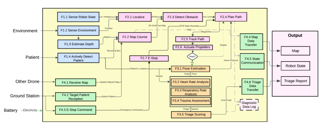
Our first step began by framing the ideal software architecture based on established robotics principles. We envisioned a sequential pipeline:
Core Pipeline Components
- Sensing
- Acquiring data from cameras (RGB/Thermal) and other sensors
- SLAM/Localization
- Building maps and determining the drone’s position within them
- Initially considered crucial for complex unknown environments
- Planning
- Generating paths for navigation and mission execution
- Tracking
- Following planned paths or dynamic targets
- Actuation/Control
- Translating high-level goals into low-level commands for the flight controller
Triage Task Logic
The core mission function, encompassing:
- Patient Detection: Finding potential subjects
- Pose Estimation: Understanding orientation
- Vital Signs Estimation: Algorithms for heart rate, respiratory rate from sensor data
Auxiliary Modules
Essential supporting functions including:
- GCS communication
- Data logging
- System health monitoring
Retrospective
The initial conceptual design later proved to be well aligned with the principal of our actually functioning software system.