PCB
Description
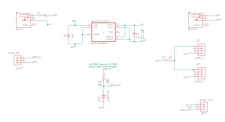
The PCB we have designed contains two circuits. The first, which is located at the top of the schematic, is a power distribution circuit. It has a 24 V input, which is split into a 24 V output, and two USB ports which can each supply up to 5 V.
The second circuit serves to step down a 24 V PWM signal to a 5 V PWM signal that is standard with most micro servos. This gives us the functionality to control the servo that unlocks and locks the user door using the ClearCore I/O controller that we have purchased for use with the pneumatic system.
Schematic
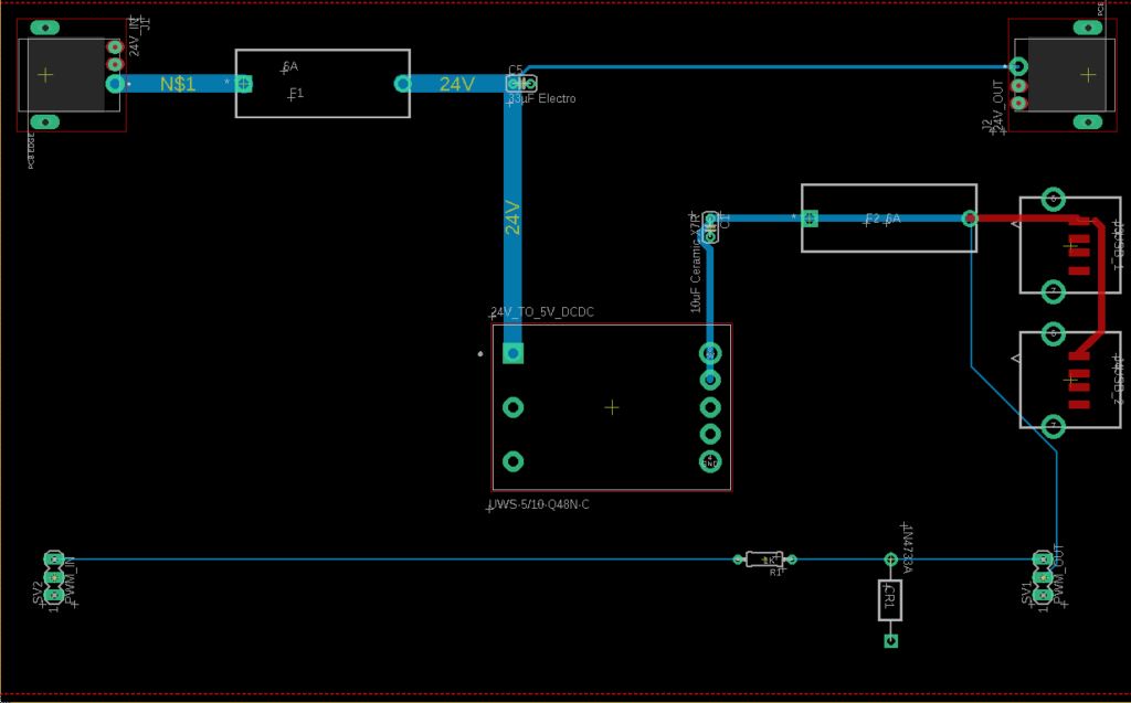
Layout
Bill of Materials
| Vendor part number | Quantity (To Order) | Value | Part Designator(s) | Vendor |
| 839-54-00255CT-ND | 2 | 54-00255 | J1, J2 | DigiKey |
| F6094-ND | 2 | 0PTF0078P | F1, F2 | DigiKey |
| F4710-ND | 1 | 0233007.MXP, 7 A | Fuse, for F1 | DigiKey |
| F2684-ND | 1 | 0235005.HXP, 5A | Fuse, for F2 | DigiKey |
| 811-2361-ND | 1 | UWS-5/10-Q48N-C | 24V_TO_5V_DCDC | DigiKey |
| 1N4733AFS-ND | 1 | 1N4733A | CR1 | DigiKey |
| SAM1111-03-ND | 2 | TS-103-G-A | SV1, SV2 | DigiKey |
| 1189-1894-ND | 1 | 10 uF | C1 | DigiKey |
| 732-8663-1-ND | 1 | 33 uF | C5 | DigiKey |
| CF14JT1K00TR-ND | 1 | 1K | R1 | DigiKey |
| 609-4413-ND | 2 | 87583-2010BLF | J3, J4 | DigiKey |
Mechanical Design
Comprising the SNAAK system are a variety of manufactured components, with a variety of techniques used for manufacturing. Below, in Tables 1 through 3, the key components and their respective manufacturing techniques are listed. For laser cut parts, DXF files are linked below, and for 3D printed parts, STL files are provided. All 3D printing was done with generic PLA.
| Assembly Instructions | 3D Viewer | |
| Vention Assembly | Instruction Manual | Vention Link |