Kiosk/Hardware System
To begin, we were provided a Franka Emika Panda mounted on top of a movable cart constructed for extruded aluminum pieces and their associated connectors. This existing structure, however, lacked the infrastructure needed to mount the overhead cameras, to house the ingredient bins, and to place the weighing scales. Additionally, after discussion with Professor Kroemer, we decided to elevate the work surface to be roughly at the arm’s shoulder joint height, as this allowed for the arm to have the best dexterity and reach. A rendering of this layout is shown in Figure 1a, with an assembled version shown in Figure 1b.


To house the ingredients, we are using 1/4 size cold drop pans. These allow us to store up to 6 ingredients and are still large enough to give the arm ample room to maneuver during the ingredient pick up process. To house these pans, as well as to support the sandwich assembly area, 1/4-inch acrylic sheets were cut to size. These sheets can be screwed onto the extruded aluminum structure.
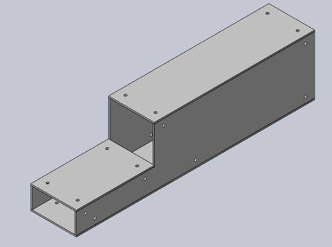
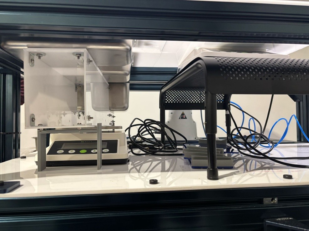
Below the work surface, we have mounted three scales. These scales, under the ingredient bins, and under the sandwich assembly area, provide information on the current stock of ingredients, as well as the weight of the assembled sandwich. To accommodate the differing bin depths, we designed the structure shown in Figure 2a. This structure allows us to read the combined weight of the ingredients in all 3 bins. Figure 2b shows the scales placed under the work surface.
To manipulate the sliced ingredients, we opted to use a high-flow suction system. This system, purchased from Piab, is capable of operating at 60 Psi, pulling 30 gal/min. With this high flow, the system is not only able to pick up meats and cheeses, but the relatively porous bread as well. A diagram of the complete pneumatic system is shown in Figure 3.
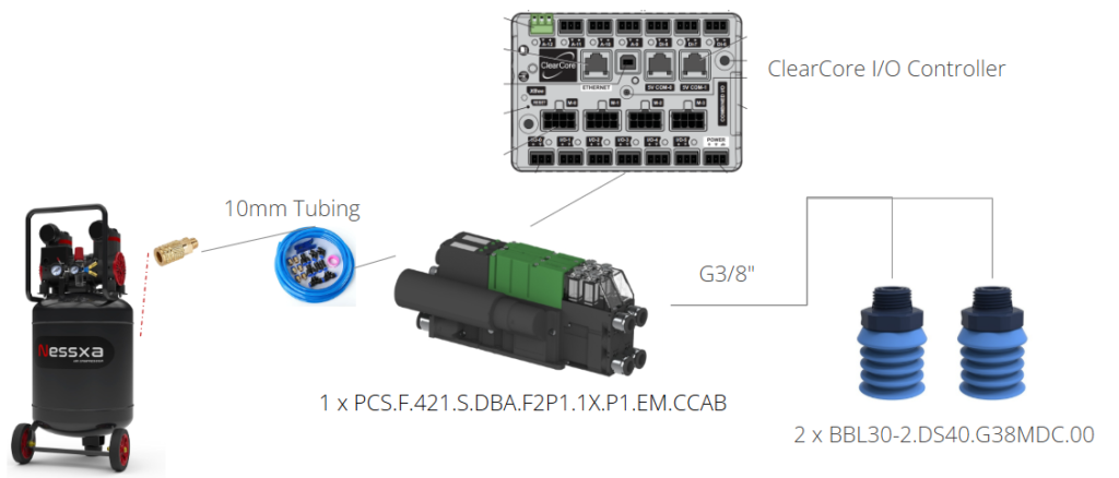
To manipulate the shredded ingredients, we have chosen to go with a claw-like gripper. The chosen gripper is pneumatically actuated and can integrate with the high-flow suction system displayed in Figure 3. To swap between gripper and sucking modalities, we have chosen to fit a high-torque servo motor to the end effector, which can swing an arm holding the gripper up and down, in order to position it properly depending on the ingredient type being manipulated. The full gripper assembly is shown in Figure 4.

Sensing
Weighing Scale
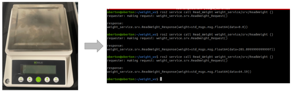
To capture the current stock of ingredients, and to determine the amount of an ingredient in the sandwich assembly area, we purchased a digital weighing scale with gram level accuracy, an upper limit of 3kg, and an RS232 interface. When prompted, the scale returns the current weight measurement. A moving median filter is also used to filter out noise in the measurement process. A photo of the scale as well as example outputs are displayed in Figure 4.
Sliced Ingredient Pick-Up Pipeline
Before an ingredient can be picked up, the location of the ingredient must be determined in the arm’s base coordinate frame. To achieve this, weh have mounted an Intel RealSense D435 camera to the Franka Panda arm. To extract the XYZ pickup location, the first step is to segment the desired ingredient from the image. In our case, this means segmenting the ingredient that is on top of the stack.
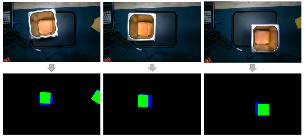
To extract a mask that represents the top layer of an ingredient, we are utilizing at UNet deep learning model. UNet, which has the ability to directly generate the segmentation mask for the top slice in the stack, was trained on the augmented form of images collected from RealSense D435, consisting of varying lighting conditions, ingredient arrangements, and bin arrangements. After generating the top layer mask, a custom image-processing pipeline calculates its midpoint. Example UNet Results are shown in Figure 5.
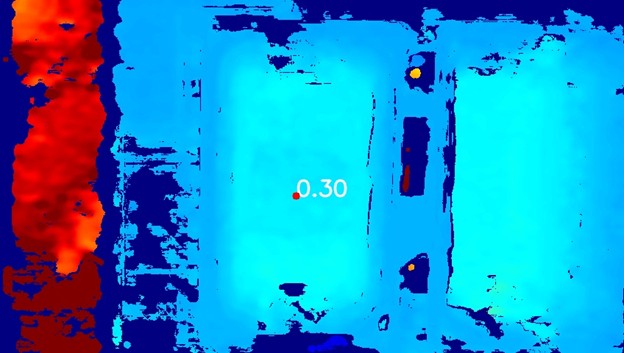
Once the top ingredient is segmented, the central point is passed through the pipeline to be used as the XY pickup location. To get the remaining Z coordinate of the pickup point, the depth functionality of the D435 is used to generate a depth map, from which the Z location of the desired point is extracted. Figure 7 displays an example depth map, including the depth at a specified pick-up point. The X, Y, and Z locations parsed from this pipeline are then transformed into the arm’s base frame, which can then be used by the manipulation system to accurately pick up the ingredient.
Sliced Ingredient Placement and Check Pipeline
After placing the first slice of bread, it is desired that all subsequent ingredients are placed at the midpoint of this slice. Therefore, after placing the first slice, a photo of the assembly area is taken, from which the location of the bread can be extracted. To localize the bread, HSV thresholding is used. After this thresholding, a contour detector locates the edges of the bread, from which the center of the bread can be ascertained. This, coupled with the depth value of the bread, is then logged for later use when placing ingredients.
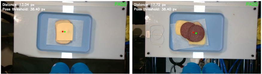
To certify that we are meeting our performance requirements, and to inform the decision making of the state machine, we introduced a feature to automate the process of validating ingredient placements. To begin, we used the same UNet and classical approaches that were used to find the ingredients in the bin to find them in the assembly area. The distance between the center point of the bottom bread to the center point of the ingredient mask is then used to determine if that specific ingredient is within tolerance (3 cm). An example output for both a slice of cheese and meat is shown in Figure 8.
Shredded Ingredient Pickup Pipeline
To pick up shredded ingredients, we have deployed an offline Model-Based Reinforcement Learning approach. Specifically, our chosen approach works by evaluating the mass that can be picked up from a 100×100 pixel patch of an RGBD image, given a fixed depth pickup location underneath the top-most point in the patch. To train this model, we collected over 5000 data points of shredded lettuce and sliced onion pickups. The data collection pipeline consisted of a UI from which the operator could teleoperate the arm and select the desired pickup point. Once selected, the arm would perform a grasp, and the weighing scales under the bins would be used to automatically log the weight picked up. We could then use the associated image patch around the selected point as the model input, and the weight picked up as the output in order to train our MBRL approach. Our chosen model architecture is shown in Figure 9.
Once trained the inference process consisted of the following steps:

- Crop the bin from the image.
- Discretize the bin image into patches.
- Run inference on the model to determine the estimated weight that will be picked up from each patch.
- Use the estimated pick-up weight and other heuristics to determine the most optimal patch.
- Convert the patch center to the arm base frame.
An example patch-wise pickup weight estimation is shown in Figure 10.

Manipulation
Ingredient Pick-Up and Placement
To pick up an ingredient, there are two operations that need to be performed. First, the arm must move into the pre-grasp position. To ensure that the arm is able to move into this pose collision free, trajectory following is used. These trajectories are generated using a minimum jerk joint trajectory solver. This solution works as our environment is relatively uncluttered.
Once above the desired bin, and the XYZ coordinate of the pick-up position is read from the sensing subsystem, the pick-up maneuver can begin. The arm first moves to an X, Y, and Z location immediately above the top of the bin, and directly above the pickup point. Next, a straight-line pose trajectory is calculated, using a trapezoidal velocity profile, with set maximum velocities and accelerations, used to determine the speed of the end effector. This desired trajectory is then tracked using an impedance controller with a low impedance in the Z direction, and the pneumatic system is enabled. The arm lowers in a straight line until it exerts a light force onto the ingredient, which is held firmly by the suction from the pneumatic system. The arm is then raised back up in a straight line to the original pre-grasp location, from which it can continue on to place the ingredient on the sandwich.
After picking up an ingredient, the arm follows a prerecorded trajectory to a point above the assembly area. The arm then descends, using an impedance controller, to the desired placement point specified by the vision subsystem, and ejects the ingredient.
One issue that we encountered, was a slight mismatch, between the desired height of the end effector, and the eventual position that the end effector reached. While this varied based on the location, this was generally a problem when descending lower than the elbow joint. Due to the precise nature of the pickup and placements, we used iterative learning control to negate this offset. During execution, the arm determines the distance between the desired and actual height and uses this to continually update an estimation of the offset parameter. The below equation governs this process, where alpha is the learning rate:

Collision Checking and Virtual E-Stop
Throughout the arm’s movement, it is important that the arm, as well as end effector, do not collide with the workspace or itself. To prevent any collisions, we have defined the workspace, including the ingredient bins, in our program. During any motion of the arm, there is constant collision checking, which triggers a stop in motion if any collision is detected.
Additionally, we desired to ensure that the arm would never move while operators or the customer were interacting with the workspace. To accomplish this, we have set a enable flag for all arm operations, that blocks access to all of the ROS actions to the arm while set.
Backend
Communication
Our system is built on top of the ROS2 Humble framework. The sensing, manipulation, and pneumatic subsystems publish their services and actions on this framework, which are then called by the state machine. This allows for extreme flexibility, and the modularization of the system.
State Machine
To coordinate the construction of a sandwich, we are using the state machine architecture. This state machine is implemented in ROS2, using the YASMIN package. The current state diagram for SNAAK is shown in Figure 11.
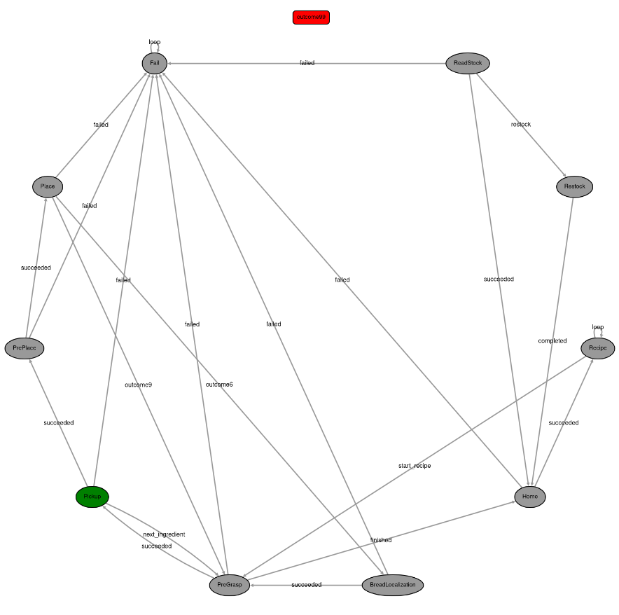
Not only does the state machine include the desired behavior assuming ideal results, but it is able to use sensor date from the camera and weighing scales, to detect errors in execution. After an error is detected, recovery behaviors are triggered to either alert the operator to the presence of an error or rectify the error automatically.
User Interface
Paired with the state machine is a User Interface, which handles receiving inputs from the user and operator. This user interface has two pages. The first of which is the user page, displayed in Figure 12. This page allows the user to select their desired quantity of each ingredient that is in stock. It also displays the nutritional information (calories) of their sandwich, as well as the progress of the assembly.

The other page of the UI is the operator page. This page serves two purposes. First, it provides the infrastructure for restocking the kiosk, allowing the operator to select which ingredient they are placing in each bin. Additionally, it provides debugging information, allowing the operator to get real-time insights into the workings of the SNAAK system.
