Team Presentations & Reports
| Name | Presented on | Presentation | Report |
|---|---|---|---|
| Project Progress on Systems Engineering | Oct 29, 2024 | Link | |
| Conceptual Design Review | Dec 5, 2024 | Link | Link |
| Progress Review #1 | Feb 13, 2025 | Link | |
| Progress Review #2 | Feb 27, 2025 | Link | |
| Preliminary Design Review | Mar 11, 2025 | Link | |
| Progress Review #3 | Mar 20, 2025 | Link | |
| Progress Review #4 | Apr 8, 2025 | Link | |
| Critical Design Review | Apr 28, 2025 | Link | |
| Project Management Review | Sep 8, 2025 | Link | |
| System Development Review | Oct 20, 2025 | Link | |
| Standards & Regulations presentation | Nov 3, 2025 | Link | |
| Fall Validation Demo | Nov 24,2025 | Link | |
| Public Presentation (poster) | Dec 3,2025 | Link | |
| Final Report | Dec 10,2025 | Link |
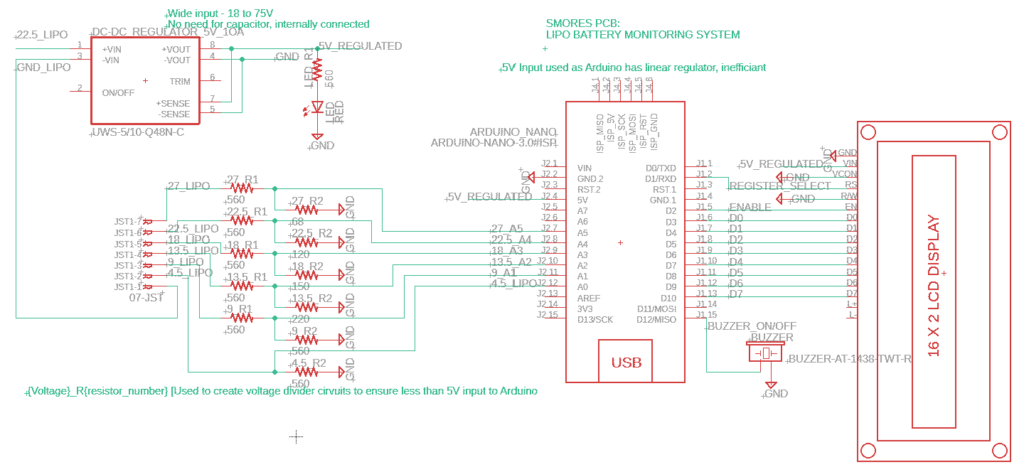
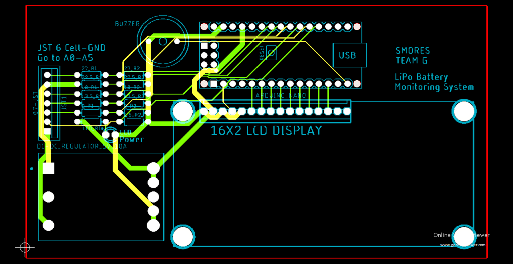
PCB Assignment
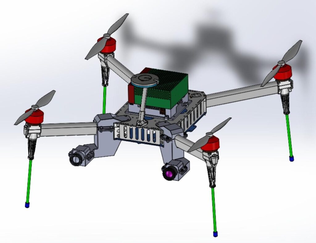
Since our drone platform is built from the Hexsoon EDU-650 frame kit, a custom power distribution board (PDB) was included with the system. Instead of replacing the professionally-made PDB, we decided to implement another function that is critical to our project: battery voltage monitoring.
Ensuring that a LiPo battery is within its operating voltage range is a safety-critical application. The safety requirement of the operating voltage for a LiPo battery is between 3.2V/cell and 4.2V/cell. The ideal operating voltage per cell for a LiPo battery is around its nominal voltage of 3.8V/cell. Overvolting (some cell has a voltage greater than 4.2) and undervolting (some cell has a voltage less than 3.2V) cause permanent damage to the battery, reduce its lifespan and make it susceptible to volatile behavior such as smoking or catching fire. However, overvolting a battery can only happen during charging and we rely on good quality chargers that balance the battery while charging. Hence, we will focus on preventing undervolting.
Our team is planning on making a printed circuit board (PCB) that can do the following:
- Detect the voltage of each cell in a 6 cell (6S battery)
- Provide a visual and an audible alarm when any cell reaches below 3.2V
- Have an LED display that shows the current voltage of each cell and total battery voltage in rotation.
Schematic
Layout
Individual Learning Reports (ILRs)
| Aayush Fadia | Abhishek Iyer | Amy Jiang | Ranai Srivastav | Swastik Mahapatra |
|---|---|---|---|---|
| ILR01 | ILR01 | ILR01 | ILR01 | ILR01 |
| ILR02 | ILR02 | ILR02 | ILR02 | ILR02 |
| ILR03 | ILR03 | ILR03 | ILR03 | ILR03 |
| ILR04 | ILR04 | ILR04 | ILR04 | ILR04 |
| ILR05 | ILR05 | ILR05 | ILR05 | ILR05 |
| ILR06 | ILR06 | ILR06 | ILR06 | ILR06 |
| ILR07 | ILR07 | ILR07 | ILR07 | ILR07 |
| ILR08 | ILR08 | ILR08 | ILR08 | ILR08 |
| ILR09 | ILR09 | ILR09 | ILR09 | ILR09 |
| ILR10 | ILR10 | ILR10 | ILR10 | ILR10 |
Design Brainstorming
Drawings, schematics, datasheets
Electrical
All electrical documentation, wiring diagrams, schematics, datasheets can be found at this documentation link: https://airlab.slite.page/p/ppKdwPyX3i36hc/Electrical-Connections
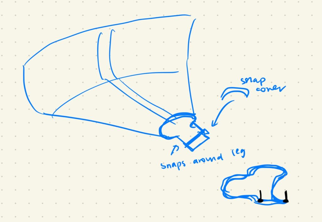
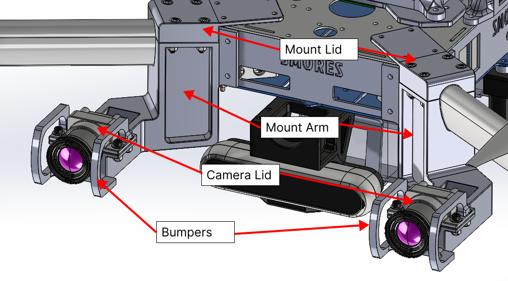
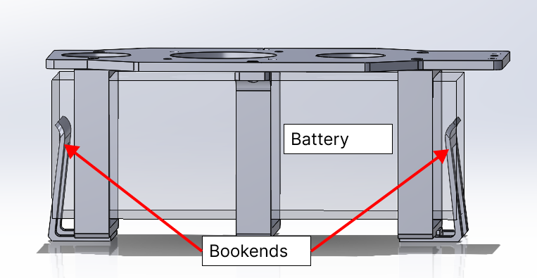
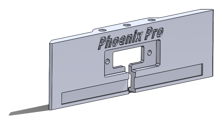
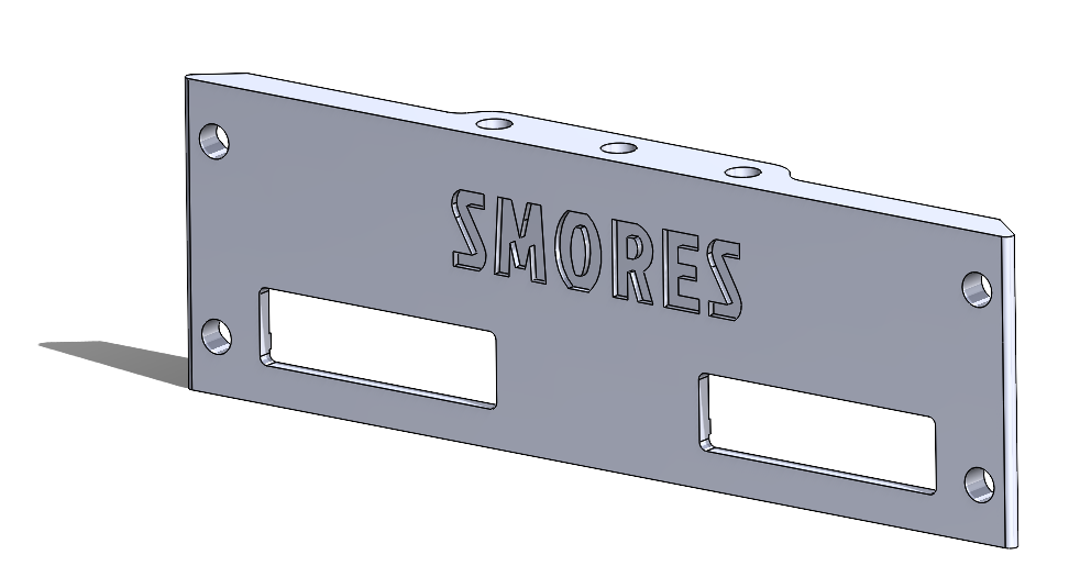
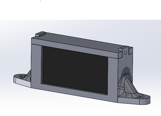
Mechanical
Datasheets
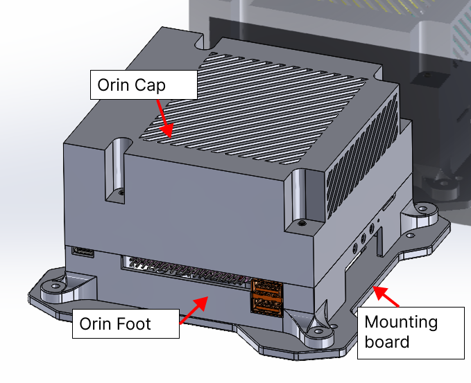
NVIDIA Jetson AGX Orin Developer Kit Carrier Board Specification
TELEDYNE FLIR BOSON AND BOSON+ THERMAL IMAGING CORE PRODUCT DATA SHEET
Epson M-G365PDC1/PDF1 Data Sheet
Frsky X7 X7S ACCESS Transmitter Manual
Component testing & experiment results
Software
The codebase is built in ROS2 and hosted in the following Github repos:
- https://github.com/castacks/smores_drone_software: Houses higher-level algorithms and system-specific configuration files.
- https://github.com/castacks/smores_drone_drivers: Houses low-level sensor initialization software.
- https://github.com/MAC-VO/MAC-VO-ROS2: Houses MAC-VO, the onboard odometry algorithm.
The entire software stack can be initialized with the launch.sh bash script in the smores_drone_software repo. This script will open a tmux session that brings up all sensors (thermal cameras, realsense, IMU), initializes MAC-VO odometry with the appropriate configuration, initializes dense depth estimation with FoundationStereo, initializes global mapping via Octomap, and finally opens Rviz and the combined camera feed visualizer. Additionally, the tmux session will include several windows that run ROS debugger commands to the relevant topics such as ros2 topic echo and ros2 topic hz so that the user can verify all components of the software stack are running as expected and easily debug as necessary.