Objectives Tree

System Requirements
The system requirements for the Lunar ROADSTER project are derived from a comprehensive understanding of the problem statement, its use cases, and the high-level objectives. The requirements are organized into mandatory and desirable categories, further classified into functional, performance, and non-functional requirements. The mandatory requirements form the core functionalities essential for the project’s success, while the desirable requirements, though initially out of scope, aim to enhance the system’s overall performance. The requirements may evolve as the system develops, further research is conducted, and tests refine the design. The team will focus on meeting all mandatory requirements by project deadlines while working to implement desirable ones as resources permit.
Mandatory Functional Requirements
| Sr. No. | Mandatory Functional Requirement |
|---|---|
| M.F.1 | Shall perform trail path planning |
| M.F.2 | Shall operate autonomously |
| M.F.3 | Shall localize itself in a GPS denied environment |
| M.F.4 | Shall navigate the planned path |
| M.F.5 | Shall traverse uneven terrain |
| M.F.6 | Shall choose craters to groom and avoid |
| M.F.7 | Shall grade craters and level dunes |
| M.F.8 | Shall validate grading and trail path |
| M.F.9 | Shall communicate with the user |
Mandatory Performance Requirements
| Sr. No. | Performance Metrics |
|---|---|
| M.P.1 | Will plan a path with cumulative deviation of <= 25% from chosen latitude’s length |
| M.P.2 | Will follow planned path to a maximum deviation of 10% |
| M.P.3 | Have a contact pressure of less than 1.5 kPa |
| M.P.4 | Will avoid craters >= 0.5 meters |
| M.P.5 | Will fill craters of up to 0.5 meters in diameter and 0.1m in depth |
| M.P.6 | Will groom the trail to have a maximum traversal slope of 5° |
Mandatory Non-Functional Requirements
| Sr. No. | Parameter | Description |
|---|---|---|
| M.N.1 | Weight | The rover must weigh under 50kg |
| M.N.2 | Cost | The cost for the project must be under $5000 |
| M.N.3 | Computing Capacity | The onboard computer should be able to run all required tasks |
Desirable Non-Functional Requirements
| Sr. No. | Parameter | Description |
|---|---|---|
| D.N.1 | Technological Extensibility | The system will be well documented and designed so that future teams can easily access and build on the work |
| D.N.2 | Aesthetics | Requirement from sponsor, the rover must look presentable and lunar-ready |
| D.N.3 | Modularity | To enable tool interchangeability, the tool assemblies must be modular and easy to assemble/disassemble |
| D.N.4 | Repeatability | The system will complete multiple missions without the need of maintenance |
Functional Architecture
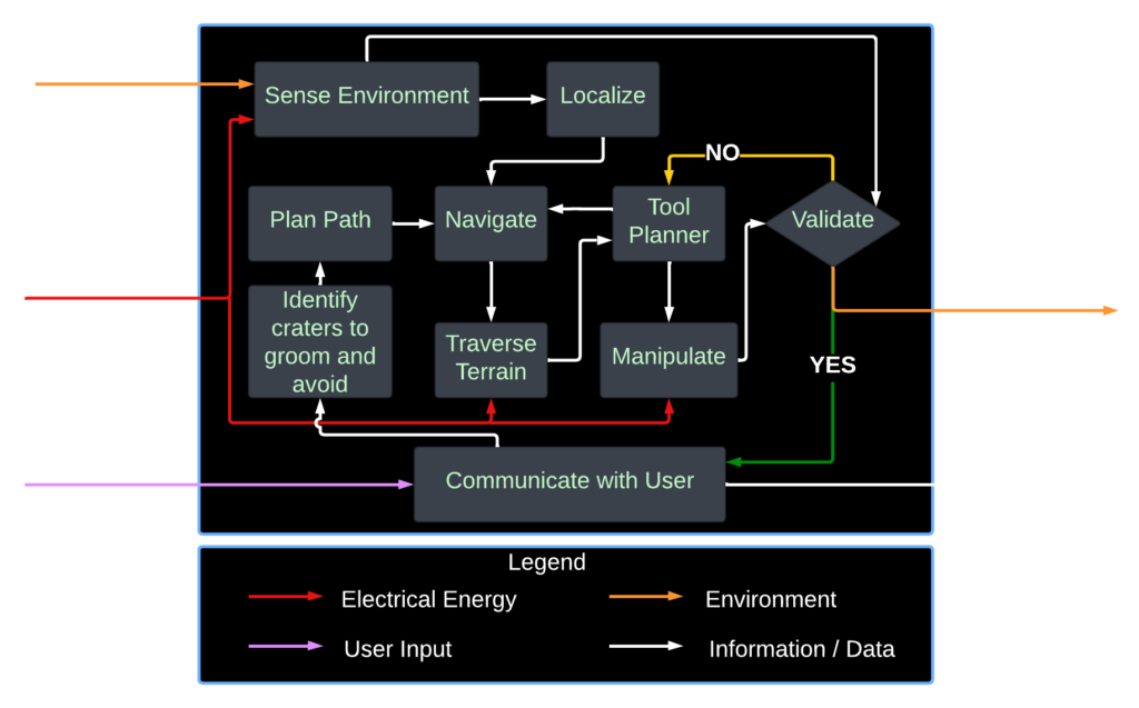
The figure below illustrates the functional architecture of our system. The system receives three types of input: user input in the form of a map of the environment from the operational terminal, battery input as the electrical energy that powers the components, and environment input from the moonpit (worksite).

Cyberphysical Architecture
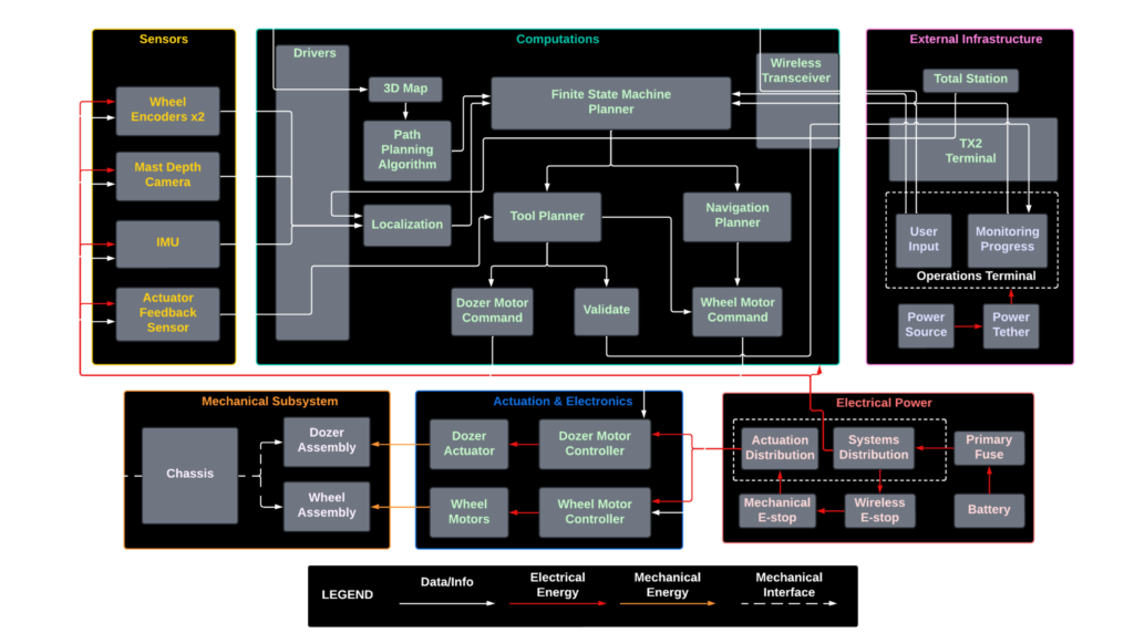
The cyberphysical architecture, depicted below, shows how our Lunar rover is physically realized. It integrates a network of the following major subsystems: Sensors, Computations, External Infrastructure, Mechanical subsystem, Actuation and Electronics, and Electrical Power. Each component plays a specific role, with all of them working together in unison to meet the unique demands of lunar surface operations.

System Design Description

Rover
Building up on the work of the MRSD 2022 Team Crater Grader, we will be using the same RC4WD chassis as our Lunar rover. Its wheels are driven through front and rear differentials, with independent steering of the front and rear axles in a double Ackermann configuration. The rover will house all the sensors, excavator tool assembly, electronics and compute required to perform the autonomous trail grooming tasks.
The Moon’s terrain is relatively flat with 67% of routes at less than 5° in slope and 91% less than 10°. It is possible for rovers to traverse over 15-20° slopes, although for angles exceeding 15°, the slip would likely exceed 30%. Taking this into consideration and also our desirable vehicle mass of less than 50 kilograms, we will be sourcing appropriate wheels for the rover, so as to match our requirements.
Excavator
From our subsystem-level trade study on choosing the best Moon-working manipulation option, we have decided to use a front loader to perform the grooming operations. This strategy draws on proven practices from Earth-working machines used for construction and mining. By adapting this terrestrial knowledge to the Moon, where conditions are harsher and maintenance opportunities are limited, using such an excavator tool provides significant advantages for effective trail preparation.
The excavator will be present at the front of the rover and will perform the bulk handling of the Lunar regolith. We will be designing the excavator with multiple degrees of freedom (DOFs) to enable flexible and fast grooming operations on the varied Lunar terrain. Their operation will depend on several functional parameters, which include:
- The assembly will adjust their position and orientation based on the unevenness of the terrain
- The assembly will dynamically adjust their angles and positions relative to the rover’s pitch, roll, and yaw to maintain proper contact with the ground
- The assembly will adjust their operation to achieve the desired grooming metrics
Sensors and Electronics
A ZED 2i stereo camera will be mounted on the mast of the rover at an optimal height and facing the ground for active mapping of the environment. The height will be carefully chosen so that the camera’s field of view (FOV) is not hindered by the front excavator assembly. An IMU sensor will be mounted at a position that will minimize exposure to vibrations due to system operation. Wheel encoders will be used to determine wheel velocities, and tool encoders to control the excavator assembly. Roboclaw motor controllers will be used to control the motors. In order to validate the grooming operation, we plan on having another depth camera placed on the belly of the rover, pointing vertically downward. However, this approach is still under exploration, with potential consideration of alternative sensors for improved validation.
Software
The software architecture of the system is structured into four key modules: localization, perception, planning and control. We will be using an NVIDIA Jetson AGX Xavier Dev Kit running ROS2 for the primary computations, along with an Arduino Due for lower-level interface with the sensors and actuators. Communication between the Jetson and the Arduino will be facilitated by Micro-ROS.
A FARO Survey LiDAR will be used on the MoonYard to generate a 2.5-D map of the demo area, providing a detailed representation of the terrain. This map will serve as the basis for a path-planning algorithm to compute a navigational path for the rover to follow. These tasks will be performed in the operations terminal, that is, our laptops, which will then be fed into the rover.
Sensor data from the IMU, motor encoders, and pose estimates from the robotic total station, will be subjected to pre-processing to reduce noise. This data, along with data from the mast depth camera are fused together using an Extended Kalman Filter to localize the rover within the work site.
A finite state machine (FSM) planner will manage the high-level decision making by switching between the tool planner and the navigation planner. Within the tool planner, the excavator handler will manage the specific manipulation tasks of excavating the Lunar surface. They will individually plan the required depth of cut, assembly velocity, and the velocity of the mobile base to excavate or grade the surface. The navigation planner will include a heuristic-based graph search planner that can plan a feasible path to the desired robot pose for filling the crater and grooming the surface. The mast depth camera, which is used for actively mapping the environment, will aid in navigation. The planners send motor commands to the motor controllers.
Once a grooming operation is completed, another depth camera will be used to validate the grooming, i.e., whether the crater has been excavated or graded to a satisfactory extent according to our performance requirements. This information is fed back into the FSM planner as feedback, which repeats the entire process if necessary.
All the planners – excavator planner and navigation planner, will first be simulated on Gazebo, and then deployed into the real world.
External Infrastructure
The external infrastructure includes elements which are not present on the rover but are essential for operation. It comprises a robotic total station, which provides precise robot pose estimates to localize the robot within the environment by tracking a prism placed on its mast, a wireless transceiver, and an operations terminal for seamless communication between the rover and mission control, by providing a user interface to monitor progress and receive updates. It also includes a FARO Survey LiDAR to map the environment and also to evaluate the worksite configuration.
Integration and Testing
The project will be tested in the MoonYard, a sandbox situated in the Planetary Robotics Lab (PRL) at CMU, which is commonly used to test Space Robotic systems. Adopting a V-model for system development, we will rigorously test every unit, subsystem, and the fully integrated system at each stage of the project. Unit and subsystem tests will be considered successful based on their functionality and performance against design expectations. The success of the system level tests will be based on the metrics or performance requirements that we have set and the rover’s overall performance for grooming operations will be evaluated using the FARO LiDAR. We also aim to document every detail of the project so that future teams can easily build upon our work.