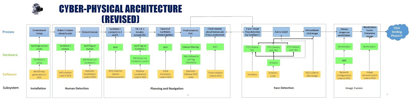
The cyber physical architecture is in complete synchronization with the functional architecture. To make it easier to get the whole idea, the cyber-physical architecture is divided into the same 3 subsystems Human detection, planning-navigation & Face-smile detection. The design of the cyber physical architecture is such that it extends the functional architecture to give a realization of methods/tools used for getting done the functions involved. It depicts the software and hardware components used in each subsystem to complete the tasks expected.
Now we will look at these parts one by one. The installation box is not technically a sub system. It just explains the basic installation procedure before putting the system to work. When the Turtlebots are installed in desired fashion in the specified room, the robot 1 initiates the self -rotation to find the person of interest. All the persons in the rooms are required to carry an April Tag on their shirt for the experiment. The self-rotation of Turtlebot 1 will be carried out using a self -rotation node written in ROS, which will be fed to the Turtlebot motors. The pan tilt unit cameras mounted on the Turtlebot 1 will then try to detect the first person with April Tags on his chest. This will be carried out using the human localization code written in ROS. When the human is detected by the pan tilt camera unit on the Turtlebot 1, the robot will discontinue rotation and will stop at its place. It will then communicate with other 2 Turtlebots over Wi-Fi. This communication will initiate the working of the Turtlebots 2 & 3. They will then localize the linear and angular position of the Turtlebot 1. This will be achieved by the detection of April Tags mounted on the Turtlebot 1, by the pan tilt camera units mounted on the Turtlebots 2 & 3. These 2 Turtlebots, in this way, will estimate the position of Turtlebot 1 and will navigate toward it. They will stop after reaching the desired relative position with respect to the Turtlebot 1. The 3 robots will form a flock in this way, as a result of the flock formation node written in ROS. The flock, as a system, will then start navigating towards the detected person of interest. It will stop navigating once it reaches the desired ‘1 meter away from human’ position. This completes the working of the human detection followed by the working of the planning-navigation subsystem.
When the system reaches desired position with respect to human, the pan tilt unit on the robot 1 will try to detect the face of the human. This will be carried out using the face tracking algorithm written in Arduino IDE format which will be fed to the pan tilt motors through the Arduino Mega microcontroller. If the face is not detected, the system will conclude that the face of the person is turned in some other direction. After this observation, the flock system will perform a rotation around the human, considering human as an axis of rotation. During this rotation, the pan tilt camera unit mounted on the Turtlebot 1 will keep performing its motions to detect the face of the person. The system will stop rotating once it detects the person’s face.
After the face detection, the system will try to detect the expressions of the person. The expression detection part will be carried out by the IntraFace software, active only on the computer of the Turtlebot 1. The IntraFace will try to find the expression of the person of interest. When it recognises that the person is smiling, it will try to find the smile estimate as a percentage value. This is an inbuilt facility offered by IntraFace. When this percentage exceed a threshold value of 80 %, the system will issued a command to click photo. This will be done by the combination for the face tracking Arduino code, the face & expression detection IntraFace facility and the photo capture ROS node. The command to capture the photo will be issued to all 3 cameras. It should be noted that the pan and tilt movements of the cameras on Turtlebots 2 & 3 are dependent and hence identical on the pan tilt movements of the camera unit mounted on the Turtlebot 1, which finds and tracks the face. Photos will be clicked by each camera individually when the capture command is issued. The clicked photos will then be transferred wirelessly (using Wi-Fi) to the workstation laptop, not mounted on the system. The ROS code written in workstation will identify the common points of the photos clicked at the 3 desired angles (-45,0,45) and perform image fusion, which is not a separate subsystem, but just an extension of the face & smile detection subsystem as shown in the figure 3. This will yield an accurate and clear smiling photo of the person, which the output of this system.