For the Fall Validation Experiment, we plan to detect the April tags mounted on the person of interest. From the depth estimate obtained from the April Tag, the robot will move towards the person and stop at a minimum distance. Following tasks have been completed in this regard:
- IMU and Gyro Calibration of Turtlebots
Calibration was done using the calibration scripts part of the standard TurtleBot ROS packages. This calibration involves having each Turtle-bot perform successive steps of increasingly large in-place rotations and measuring their wheel encoder and IMU output. When finished, the calibration indicates by what number the wheel and IMU odometry outputs should be scaled in order to better match the TurtleBot’s actual motion. We have performed this calibration on two TurtleBots. - April Tag detection-First we used the Michael Kaess C++ library for getting the proper position estimate for the April Tags. That gave us the 6 degress of freedom for the tag and its tag id. Now we have a ROS node based on this library that performs the same task and detects the tag using webcam. We referred to the light-swarm/april_tag library for this.
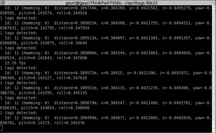
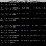 Figure: April Tag Detection topic
 - Relative Navigation: The Navigation controller node that runs on the turtlebot computer, subscribes to the April Tag detection topic and gets the relative pose of the person with respect to the camera. The z-axis starts from camera towards the April Tag, while the x- axis is towards the right and y axis points downwards. The navigation controller node than tries to reduce the relative z distance and the relative yaw angle between the camera and the April tag by publishing angular z and linear x velocity to the Turtlebot. A proportional controller was used to tune smoothly from stop to acceleration to steering to stopping again. The Navigation node moves the Turtlebot towards the person wearing April Tag until the z- distance or the distance of the April tag from camera is 100 cm or 1 m and the relative yaw is close to zero (between -5 to +5 degrees).
SPRING SEMESTER PROGRESS
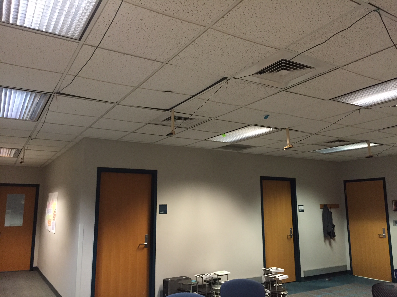
- Overhead Localization- After building the single system robot navigation subsystem, the swarm navigation system requires the robots to know the position of other robots. This localization will be done using global cameras mounted on the ceiling of the lab (Advanced Agents Lab). Four wide angle lens camera are mounted on T shaped wooden mounts. These cameras are 4-5 feet away from each other such that the entire lab room is covered. They are placed such that between two consecutive cameras next to each other there is an overlap region so there are no blind spots in the room. In each of these overlap regions April tags are glued to the carpet. These April Tags serve the purpose of automated external calibration of the cameras with respect to each other such that in the event of certain changes in orientation of the cameras, one just has to launch the automated calibration file to get them calibrated extrinsically. The intrinsic calibration was done when the cameras were bought by the. The cameras are calibrated intrinsically and manually by members of the lab. The overhead localization node is launched every time one turns on the ros system and with it all the cameras are initialized and extrinsically calibrated. One of the April Tags glued to the ground is considered to be the global origin and all the transforms and April tag detection regardless of the camera that detects it is calculated in the frame of this origin.
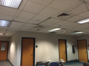 Figure: Overhead camera setup
 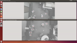 Figure: April tags detected in common region(door region is common)
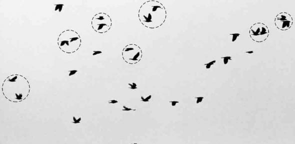
 - . Flocking- The algorithm basically is based on bio-inspired school of fishes or a flock of birds. The intuition is that the birds when they fly are unaware of the entire world i.e. they do not know the position and velocities of all the birds in the flock but only of those around them. The birds while they flock do not collide with one another, thus they may change their velocity direction when they come too close to the other bird. The birds also move around with almost same velocity. Based on these observations, Reynolds devised a model with three functions that these birds would follow. The functions are as follows.
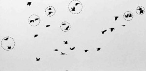 Figure: Bio-Inspired flocking
Cohesion:
The velocity and the trajectory of the agent in question is only affected by those near it. Thus we define a certain R_attract as a circular approximation to the area within which an agent could affect other agents velocity. In other words we only consider the agents within this circle with the agent in question as the center.

Function Cohesion
{
agent_in_Question.Vel=0;
For each agent != agent_In_Question
(if dist(agentagent_In_Question)< R_attract)
{
agent_In_Question.Vel+=(Agent.Vel agent_In_Question.Vel)
//same for y
}}
Repulsion:
To avoid colliding with each other the agents should move away from each other if they happen to come too close to one another. So we define a R_Repel as the safeguard distance within which if the agent is found then it will experience a virtual repulsion force. So for each agent_In_Question
Function Repulsion
{
For each agent!=agent_In_Question
(if dist( agentagent_In_Question<R_Repel))
{
agent_In_Question.vel= agent.vel
//opposite velocity vecotr }
Alignment:
In this function, if the agents are within R_attract and beyond R_Repel they tend to move in a similar fashion. Reynolds defined this function as each of the agent moving towards the center of mass of the entire flock.
Function Alignment
{ number_of_agent=0;
For each agent != agent_In_Question
if (dist(agent-agent_in_Question)>R_Repel & dist(agent-agent_In_Question)<R_Attract))
{
agent_In_Question.Vel += agent.vel
number_of_agent++
}
agent_in_question/=number_of_agent;
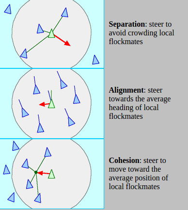 Figure: The 3 main functions that make agents flock with one another
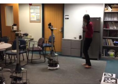 Figure: Turtlebots flocking towards the person
3. Aligning Robots around the person
In this part, as soon as the central robot reaches a distance of 1.5 meters from the person, the flocking stops and each turtlebot is independently assigned coordinates that are at -30,0 and +30 degrees about the person at 1 meter distance. Each Turtlebot then steers itself towards the respective coordinates using continuous updates from the overhead localization.
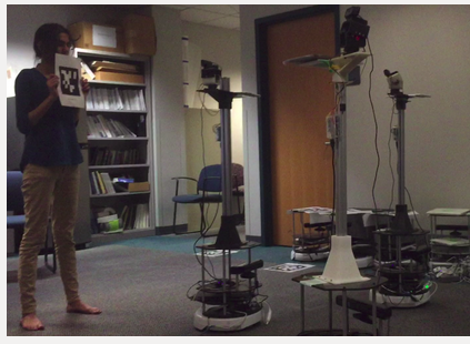 Figure: Turtlebots aligning around the person of interest at -30 ,0 and 30 degrees