Obstacle Avoidance Subsystem
The obstacle avoidance system’s main function is to detect obstacles that the robot comes across during its patrol and to direct the robot along the path of least resistance. The current system is independent of the global navigation system, but will be integrated in the future. Currently, the robot can be set to obstacle avoidance mode, where it will travel straight in the absence of obstacles but will turn either to the right, the left, or stop completely if it is blocked on both sides. The current system relies on a Hokuyo sensor mounted at the very front of the robot with a field of view 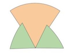 greater than 180 degrees. The Hokuyo sensor searches for obstacles in the pattern shown in figure to the right. If an obstacle is in the robot’s direct straight path, it will detect the obstacle once it is within one meter, giving the robot plenty of space to turn. The green ranges are to detect obstacles to the side of the robot and prevent the robot from turning into obstacles. Once an obstacle has been detected in any of these ranges, our obstacle avoidance algorithm will weigh the options of turning either right or left based on both the amount of points that are obstructed and their range from the robot. If there is something both to the right and to the left of the robot, giving it nowhere to turn, the robot will stop. Overlapping arcs shape for obstacle avoidance The current system is extremely robust and can be placed in a wide variety of environments. We have tested this system in the hallways of the first floor of NSH and let it wander for tens of minutes without running into any obstacles. Outside with singular obstructions in a wide open field, the system works even better. On our FVE, we were able to avoid 100% of the obstacles tested and the system made the correct decision 100% of the time. This involved moving straight when there was no obstruction, stopping when there was an obstruction on both sides, and turning appropriately when there was an obstruction on both sides.
Potential Fields Algorithm:
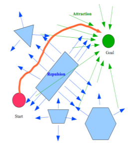
Potential field illustration:
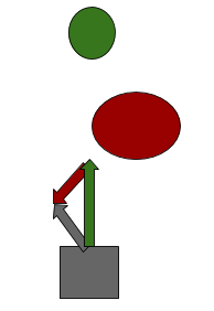
After discussion on the best algorithms that were both feasible and good for our task, we decided that potential fields was the way to go. It will allow for a simpler integration of the global and local path planning systems, allowing the global navigation code to be almost unchanged. Currently, the global navigation code creates a heading. By adding a magnitude to this heading, we can have a potential vector. Inside our local obstacle avoidance system, every point of the LaserScan will be its own vector and can be described as a two dimensional array of magnitude and angle. We have tested the integration of this susbsytem with the navigation subsystem. To solve the issue where there was interference from sunlight to the hokuyo, we switched to the Hokuyo UTM 30LX which is rated for outdoor use. However, major setback that has recently happened is the fact that our outdoor hokuyo has stopped working.
After the setback, we were able to get a new Hokuyo from Prof. Dimi. Using the new Hokuyo we were able to get the base back up and running. Using the potential fields method, we were able to get a robust obstacle avoidance. However, the only drawback of the method is the fact that our Hokuyo is only front facing. This means as the obstacle moves to the side of the robot (in the blind spot of the Hokuyo) we are no longer able to keep track of the obstacle. This might cause the robot to nudge the obstacle a little bit but not damage it.