Implementation Details
The software subsystem is broken down into the following components.
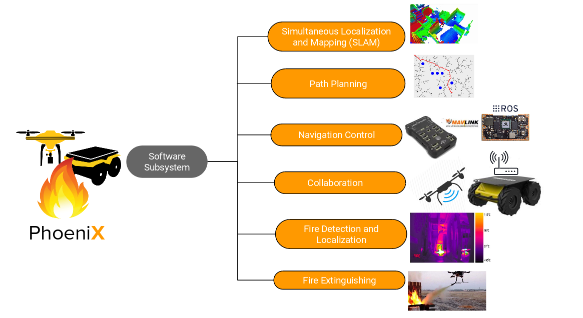 The below sections highlight the current status on the implementation of the various subsystems mentioned above. As per the project schedule the Path Planning and Collaboration subsystems are to be implemented in Fall 2019 so no progress in made in these two subsystems.
Behavior Tree Framework
The AirLab uses a smarter version of a state-machine called a Behavior Tree. Behavior trees define how a set of actions and conditions should be used to accomplish a task. The tree is made up of execution nodes, control flow nodes, and decorator nodes. Action nodes and condition nodes are the two types of execution nodes. These nodes are where the state of the system is checked and actions are performed. A condition node returns either SUCCESS or FAILURE to indicate what the state of some part of the system is. For example, an "On Ground" condition node could indicate whether or not the robot is on the ground. These are shown as the oval-shaped nodes in the figure above. Green ones indicate SUCCESS, red ones indicate FAILURE. A sample behavior tree can be seen in figure below.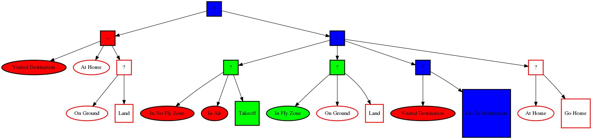
The control flow nodes determine which condition nodes are checked and which action nodes are active or inactive. There are currently 3 types of condition nodes: fallback, sequence and parallel nodes. More details on the behavior tree framework can be found here . The UAV behavior tree has actions like takeoff, detect wall, align wall, detect window, enter the window, extinguish fire, land. The AGV behavior tree has actions like drive off, detect opening, enter the opening, extinguish the fire, receive fire location, go to the fire location, extinguish the fire.
Updated SLAM Framework
To efficiently plan a path towards the fire location, we need an occupancy grid-style map of our UAV and AGV. For the AGV, we have 3 Realsense depth cameras that provide us with point-clouds, we convert them into a laser scan and pass it to ROS GMapping package [15]. The GMapping package uses AMCL (Adaptive Monte-Carlo) to localize and simultaneously create a map of the environment. We have 3 ros nodes feeding data to the package at 2Hz each. Rather than having one node which combines all the point-cloud data from the 3 cameras, we have 3 separate nodes that prevent the system for failing if any of the cameras crash. The GMapping package also takes the sensor TF from the Odom frame and the vehicle odometry in the form of a ros message and as a TF transform. It publishes a cost map of the environment that is fed to our planning subsystem. A sample cost map can be seen in figure below.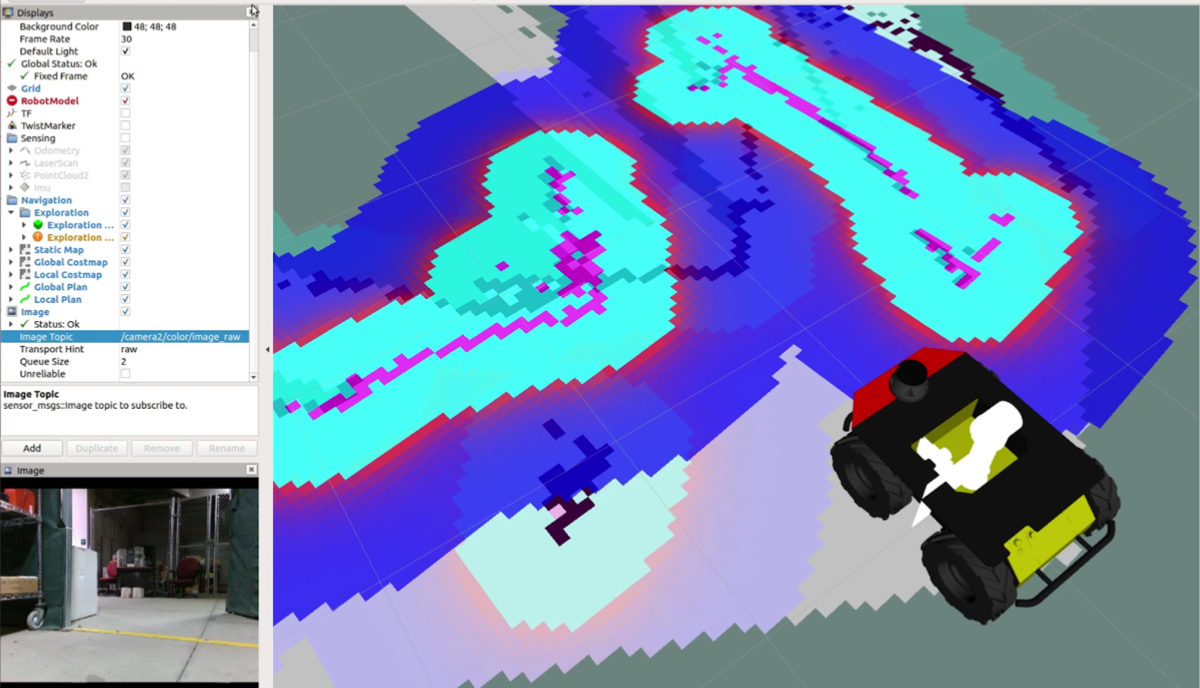
For the UAV we currently don't have any mapping pipeline, and thus it lacks features like obstacle detection and avoidance. It also relies on the fact that the opening in the building is directly in front of it, which is like a prior in our case. Also for localization on the AGV we use the robot_localization package to fuse the IMU, wheel odometry and the tracking camera data. For the UAV the localization is done using DJI's Visual Odometry pipeline using the downward-facing stereo cameras.
Path Planning subsystem
For the AGV we are using the DWAPlanner from ROS which takes the cost map from the GMapping package and runs the global and local planners. We tuned the parameters of the goal tolerance, robot size configuration, inflation around the obstacles and raytracing for obstacle path planning. For the UAV we don't have a global planner, we just have a local planner to plan a trajectory through the opening. Given the coordinates of the window center, we first position the drone in front of the window at a distance of 2m from the center and then provide 7 waypoints to go inside the room (which is approximately 1.5m beyond the window center).Window / Door Detection
Our agents need to detect a door or a window to enter the building in order to extinguish the fire. At the beginning of the semester, we used the depth images to find an opening like a door or a window using classical vision techniques. But the results were not good as the depth images from the Realsense were not good in the outdoor environment. Hence we moved towards point cloud processing where we use the line scanning method. For the UAV: we detect the dominant plane to identify the wall in the scene using the ICP method. Once the wall’s plane is identified, the desired yaw change is computed for the UAV based on the orientation of the detected wall. Finally, in the point cloud, x-axis y-axis are scanned using a sliding window mechanism to find the horizontal vertical edges of the window. For the AGV, rising and falling edge laser scan values ( r, θ ) pair is converted into ( x, y ) coordinates to get the centroid of the opening. This can be seen illustratively in figure below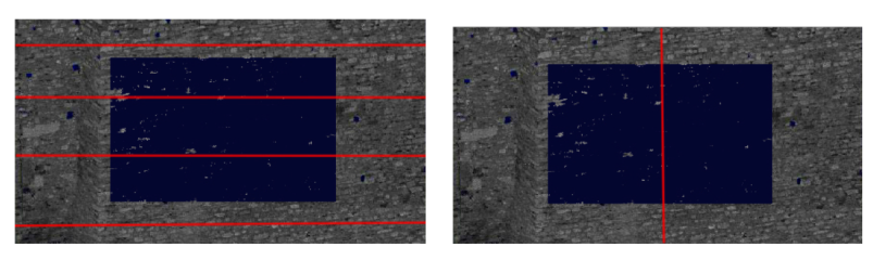
Collaboration Subsystem
Collaboration Subsystem will provide a communication link to transfer vital information such as active fire locations. This information can be extremely useful for high-level decision-making about what to do eg: explore, extinguish or return. The communication link would enable our system to fight the fire collaboratively. To establish long-range communication between the systems, we are using a TP-Link AC1750 Wireless Dual Band Gigabit Router. This router helped us with our performance requirement of maintaining communication within 25m. To send messages across agents, we used socket programming to establish bidirectional communication. Using a multi-threaded sender and receiver configuration of sockets, we were able to send data in the form of strings. We have a specific format in which the systems can send the data-casted as a string and the interpreter on the other side can get the message and convert it into ROS messages/goals depending on what task we want to perform. Currently, we are just passing fire locations across agents.SLAM Implementation Details
With our trade study we decided to use ORB-SLAM2 with a stereo camera. The reason was to obtain reliable loop-closure capability and also relocalization capability even if the SLAM system looses track of some features. Currently we have ORB-SLAM running on both the UAV and UGV. Some of the results can be seen below.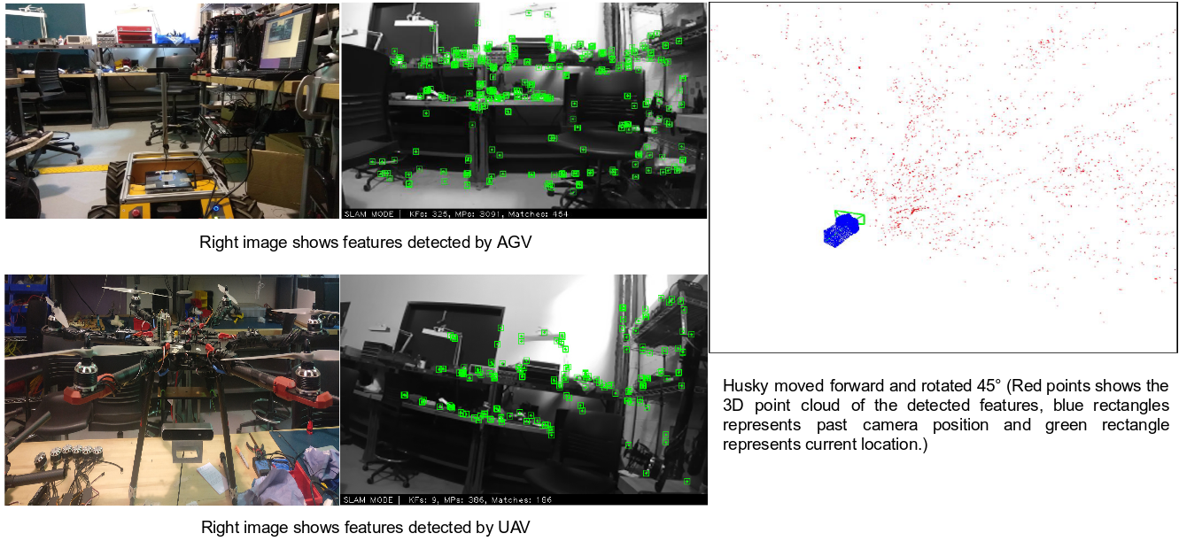
The below video highlights the performance of the SLAM subsystem when we ran it using the UAV. The trajectory and pose output by the SLAM system can be verified with the FPV of the drone.
Navigation Control Implementation Details
The team has performed mavros link setup between the PixHawk and on-board Jetson for the UAV and for the UGV we have a link between the Husky and ZOTAC computer. To perform basic maneouvers we have the infrastructure in place to basically send the commands to the systems so that we can control them autonomously. Below are some implementation details
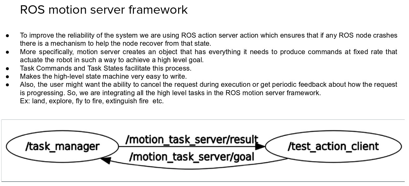
To ensure utmost safety of not only the people around the robots but also for the saftey of the robot structure we are using a ROS Action server framework which helps us to write high level tasks which can be ported on both the UAVs and UGVs so that we maintain the OOP type high level abstraction. We also write the low level command for a high level task. The framework allows us to have a safety bond between nodes such that if one of the node fails we can immediately initiate a safety sequence.
Fire detection and localization subsystem
The fire detection subsystem has the task of detecting regions of interest which is the simulated fire and simultaneously capture the location of the fire so that it can be used to update the shared database which contains the list of all the fire locations.- The subsystem uses a classical method of computer vision using various morphological operations coupled with a fusion from the RGB images obtained from the stereo pair which is onboard.
- The thermal camera captures the near infrared spectrum of the scene and which helps in segmenting the regions of high energy from the low energy resulting in some interesting interesting patterns.
- These patterns along with thresholding can give us the regions that we want but with shape approximation we can better rule out the various outliers.
- Once a region is identified we need the exact 3D world coordinates of the region which is done using the RGB stereo pair which is onboard the PhoeniX system.
The below video highlights the results obtained until April 5, 2019 for the Fire detection subsystem. Results using 3 different approaches with the last approach in cell 4 being the best performing till date.