CAD Drawings, Schematics, & Datasheets
PCB and electrical subsystem
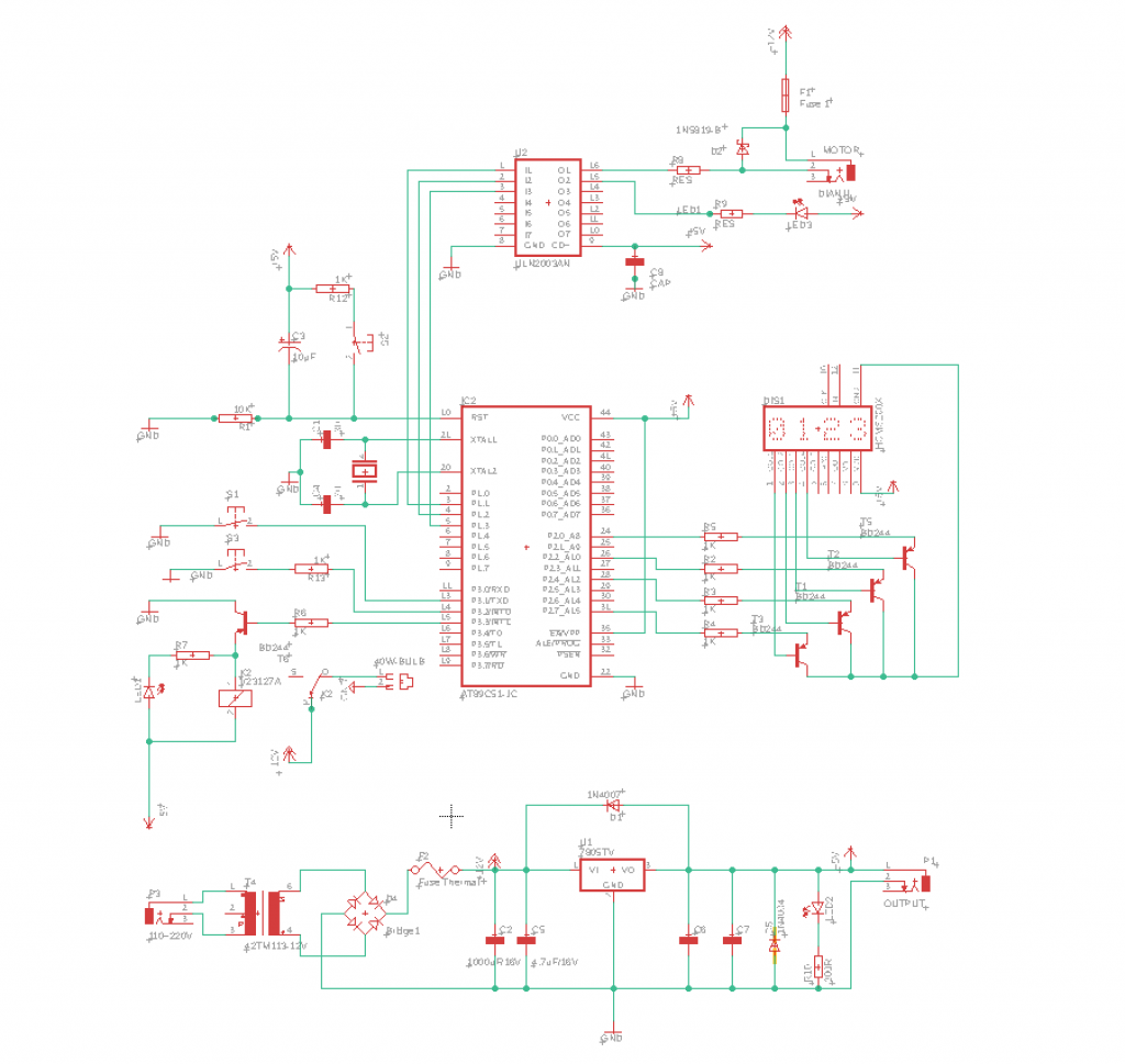
Our PCB is designed to be a power distribution system. It powers a timer, which we use to time our procedure, the motion simulation platform, and a bulb to light our workspace. The figure below shows our PCB schematic.
Design Brainstorming
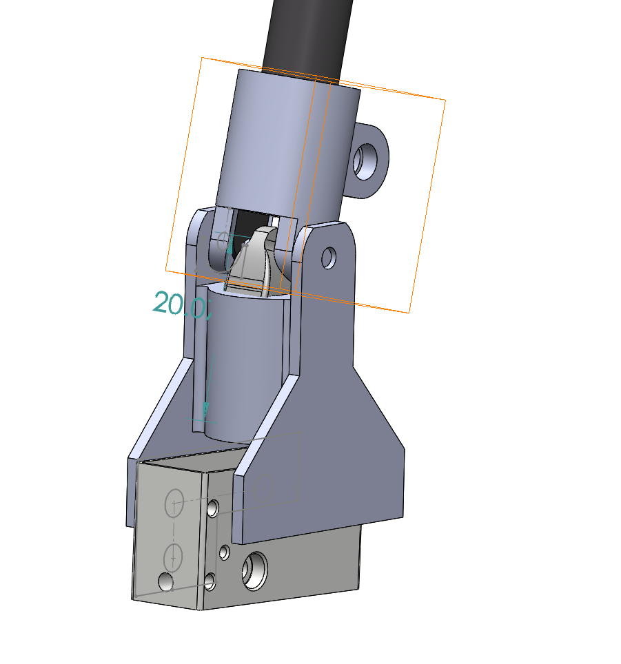
Blaser Sensor Holder Design
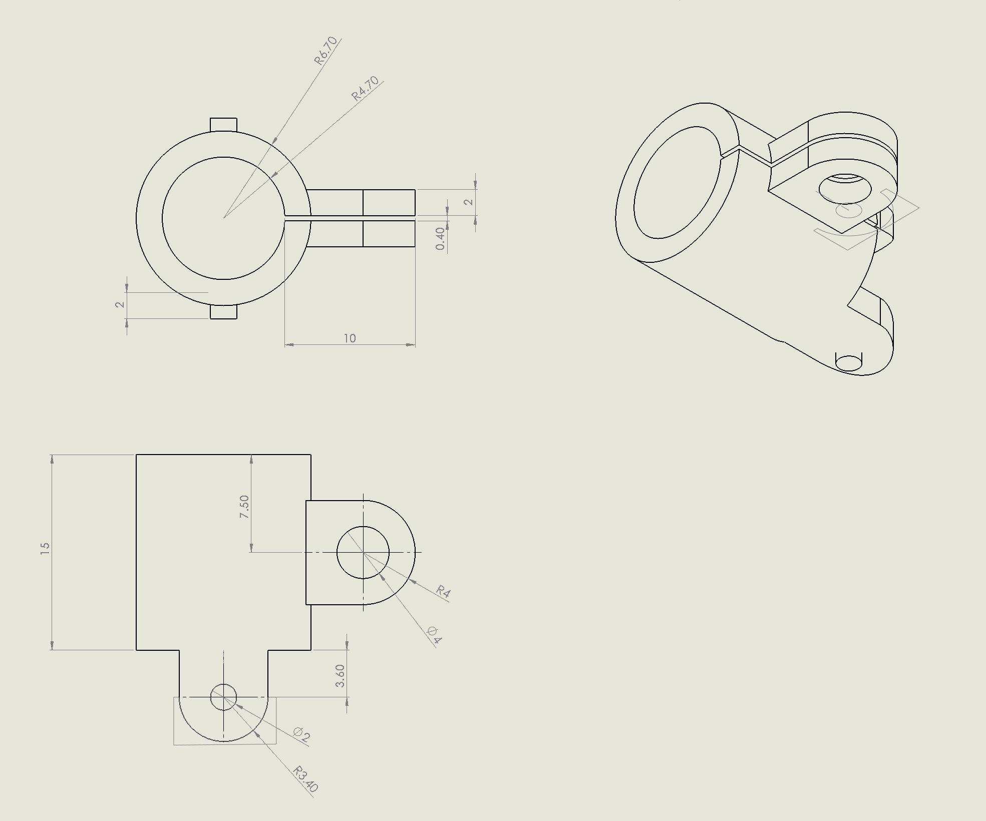
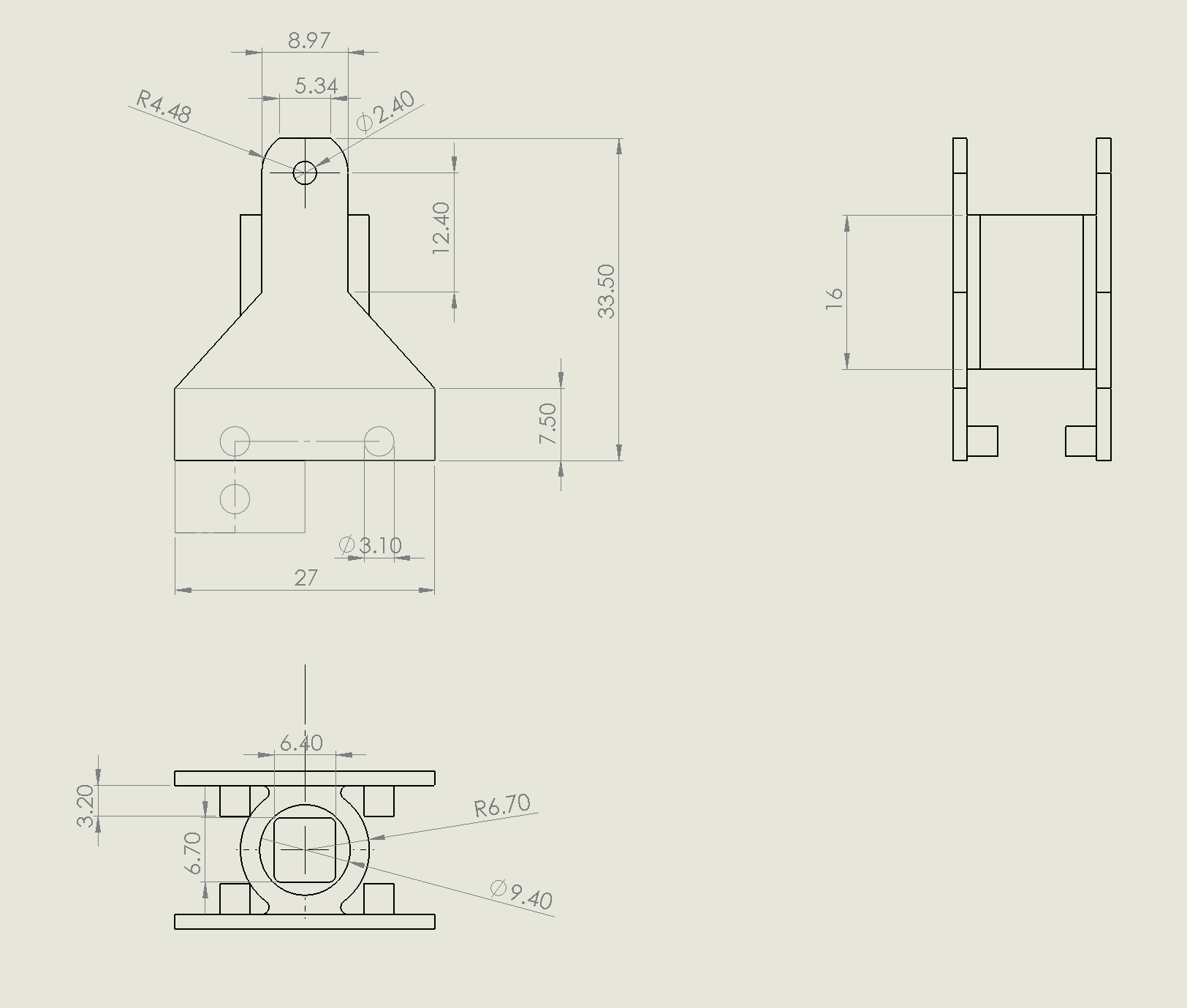
A Blaser sensor holder was designed such that the Blaser can be securely mounted on Patient Side Manipulator 1 (PSM1)of the dVRK. It guarantees that the Blaser is able to move seamlessly with the wrist of the arm. The Blaser holder consists of two parts, and a revolute joint is used to provide 1 degree of freedom to the Blaser position and orientation.
Motion Simulation Platform
The purpose of the Motion Simulation Platform (MSP) is to simulate the motion pattern of the liver due to the patient’s respiration and heartbeat rhythm during surgery. The MSP was built by emulating the work of Patel, Vatsal & Krishnan, Sanjay & Goncalves, Aimee & Goldberg, Kenneth. (2017). “SPRK: A Low-Cost Stewart Platform For Motion Study In Surgical Robotics” . The MSP has 6degrees of freedom (DOF) to move and rotate in 3D space.
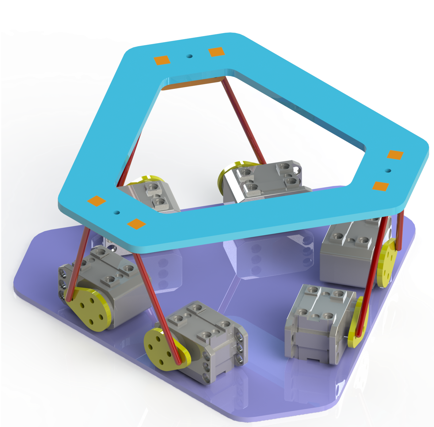
We provide the link to the Berkeley Automation github for reference. https://github.com/BerkeleyAutomation/sprk/
Software Flow Chart
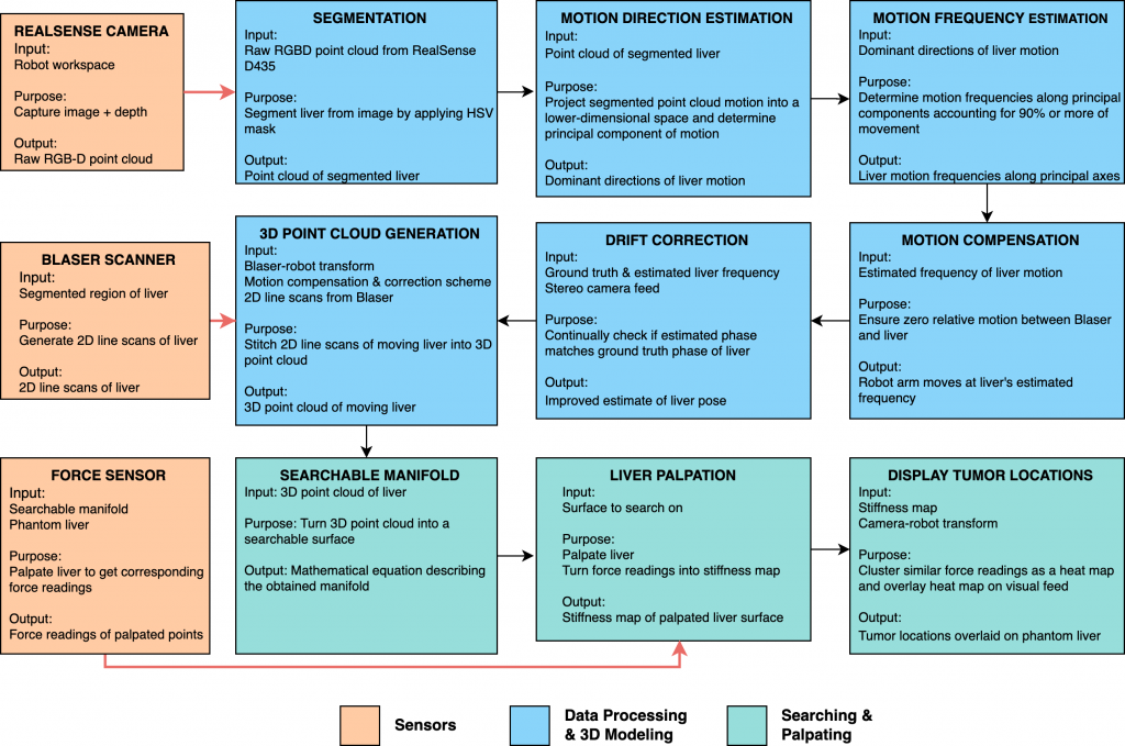
The figure below describes the flow of software control through the system in greater detail.