Electrical Subsystem/ PCB design
The following is an outline of the electrical subsystem of GRASP and the power distribution PCB.
For our hardware system, as a proof of concept for our Reinforcement Learning (RL) estimation
algorithm, will be mainly a cart equipped with a perception system and geared with manual control
for the mobility. We are planning to use an uninterruptable power supply as our main power supply,
which is connected to a transformer to step down the voltage to a constant 12V supply for the
power system PCB. The power system serves as a hub to monitor the voltages to the subsystems,
which are now planned to include a Lidar sensor, an IMU sensor, and a camera sensor. And
currently, with the main focus of the project on the viability of the algorithm and the fact that we
are using a simulated environment, we are not planning to perform highly accurate localization and
control design in the physical hardware.
We are using the uninterruptable power supply with its silent, fast, and stable feature. But
if that is not available, we could easily replace it with a Li-Po Battery for a 12V voltage input to the
power system PCB. Furthermore, for the IMU and Camera sensor, we are using the
RealSense T265 which couples both sensors in a single unit. A detailed description of the
subsystem and the power source including voltage range, continuous current, the regulation
requirement is listed in the following table:
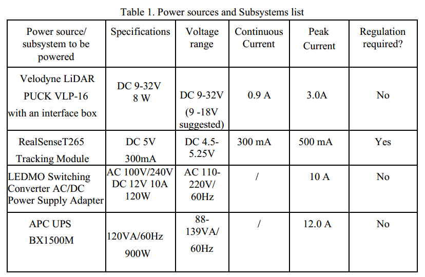
With the above table, the PCB board was designed to act as a power distribution unit which regulates the power supply for each
subsystem with details as listed below. With the schematic and board shown in Figure 1, we could satisfy the power needs for each of the
subsystems with over/reverse voltage protection.
• Lidar subsystem: For the Velodyne Puck-16 sensor, we have an interface box comes with it.
The interface box provides the over/reverse voltage and accepts 9V to 18V DC voltage. The
overvoltage is triggered at 32V and blows the 3A automatic blade fuse inside the box. Thus,
we are not providing any regulator for the Lidar subsystem due to the fact that our 12 V
input will work just fine.
• Camera/IMU T265 subsystem: For the T265 sensor, 5V DC voltage is expected. We
decided to use the MIC29300-5 regulator to provide the required voltage. MIC29300-5
takes an input voltage ranging from -20V to +60V, where our 12V DC input could fit
comfortably. The current rating of MIC29300-5 is 3A which satisfies our peak current
requirement for the T265, which is 500mA. We have also provided over voltage/current
protection with a transient voltage suppressor (SMAJ5.0) and a 1.5A fuse, which will blow
at 150% of the operating current.
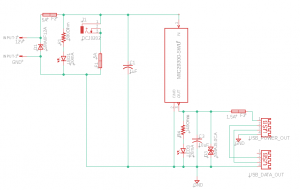
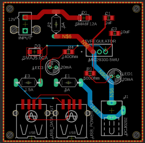
Figure 1: Power distribution board schematic and board layout
Further design concerns and mounting plan could be found at the mounting plan file attached below:
TeamD_PDS_schematic_design
TeamD_PDS_conceptual_design
TeamD_PDS_mounting_plan