Fall System Implementation Details
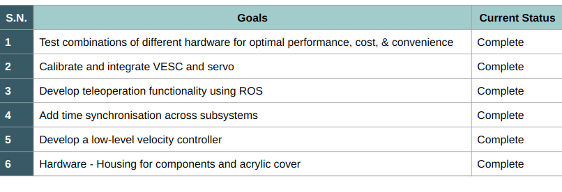
RC Car
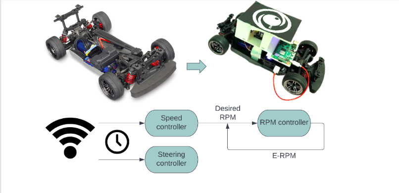
After some mechanical customization’s on the stock car, a Raspberry Pi 4B was added to act a communication module and as a interface to VESC. VESC – a motor controller from Trampa Boards was added to function as a low-level PD controller and track desired RPMs. VESC was chosen because it offers an easy to use GUI interface for tuning the controller gains and does a good job of detecting motor parameters. With a ROS node running on the Raspberry Pi, the RC can now track time stamped velocity and steering profiles sent over from the controls block.
Perception
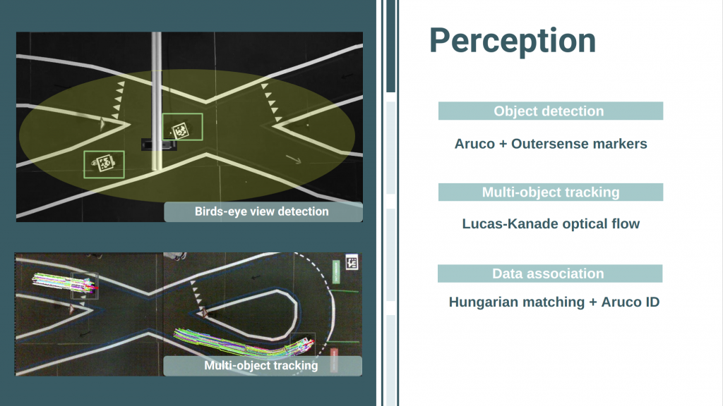
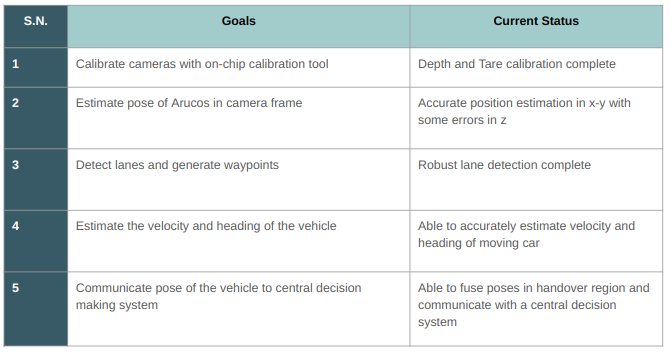
The perception subsystem consists of Intel Realsense D435i cameras mounted overhead on the track and the associated laptops acting as an edge compute device. The perception subsystem has four key components:
- Intrinsic Calibration: Intel Realsense cameras are factory calibrated but require manual recalibration for good results. This is done using an on-chip calibration tool from Intel.
- Extrinsic calibration of infrastructure mounted cameras: In multi-camera systems, a world coordinate needs to be defined so that all measurements can be converted to a common basis. This is done using AruCo markers such that the location of the first AruCo is defined as the origin and all the other poses are calculated relative to that pose.
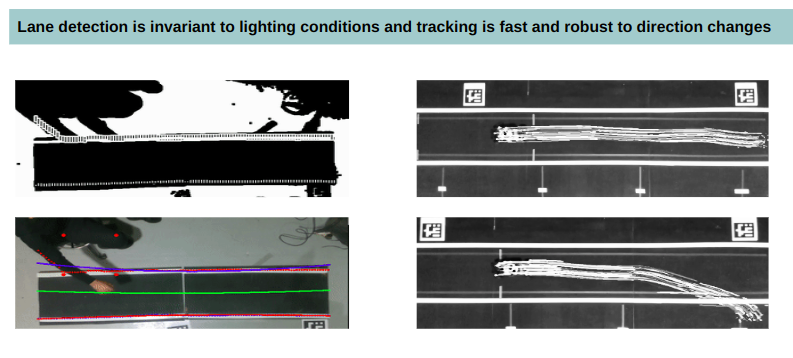
- Lane Detection: Each camera detects the lanes in its field of view, deprojects the lane pixels into camera coordinates and finally, using the camera to world transform determines the lane points in world coordinates. For lane detection, thresholding in the HSV color space followed by a sliding window approach has been used.
- Object Tracking: Each sensing unit is responsible for locating the vehicle in its FOV and communicating its estimated pose to the central decision system. Detection and tracking are decoupled because detection is computationally expensive and slower and cannot be run every frame, whereas tracking can be optimized to run at a higher frequency. For detection, the center of the Outersense logo on top of the RC car is identified using hough circle. If an object has been identified in consecutive frames, it becomes a tracked object, and a tracking ID is associated with it. Given the center of the Outersense logo from detection, an expanded bounding box covering the dimensions of the car is made. Next, this rectangle is used as a region of interest for detecting SIFT features. These SIFT keypoints then form the basis for optical flow, specifically, Lucas-Kanade Pyramidal optical flow. Solving the flow equation along with a brightness constancy assumption locates these keypoints in the next frame. Leveraging the aligned depth information from the Realsense cameras, the tracked keypoints are deprojected into the world coordinate frame. Thus comparing the location of the tracked points between two consecutive frames can help estimate the velocity and heading of the vehicle.

Decision Making System
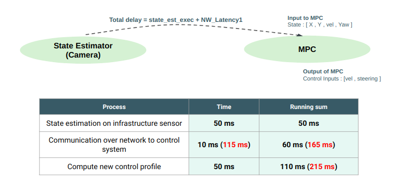
The decision making subsystem consists of algorithms for data fusion, planning, and motion cue generation. The incoming stream of data from infrastructure sensing and RC vehicles passes through a series of processing modules to output a control strategy in the form of steering and velocity signals.
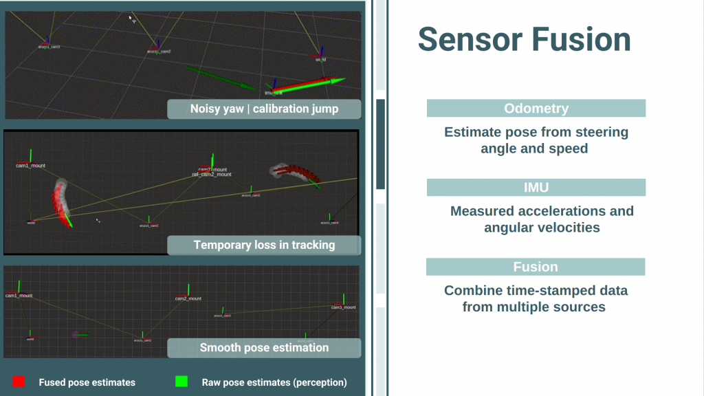
- Data Fusion: The incoming data passes through a fusion ROS node which subscribes to all the infrastructure units and listens for state estimates of the RC car. When the RC car is visible in a single camera, this node simply relays the information to the controls block. Alternatively, when an RC car is visible in multiple cameras, this node takes a mean estimate of all the incoming states and passes a single new state to the controls block.
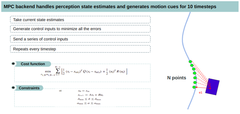
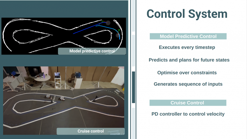
- Model Predictive Control: The goal of the decision-making system is to make sure that the RC vehicle follows the desired trajectory without deviating from the lane and goes from point A to point B at a desired speed. To achieve this, a model predictive controller is implemented, which minimizes the lateral deviation from the lane center and heading error of the RC car from the desired state by giving control commands like steering and velocity. The MPC takes in the current state of the vehicle, calculates errors for current and future states, and generates control inputs to minimize all those errors. The central system then sends these control commands to the vehicle and repeats the process every timestep.
- Motion cue generator: MPC being a finite horizon controller, it generates control inputs for the next 10 timesteps (tunable parameter). In addition to these control inputs, a halt profile is appended to each of the velocity and steering commands so that the vehicle can come to a graceful stop in case of communication loss.