
Infrastructure:
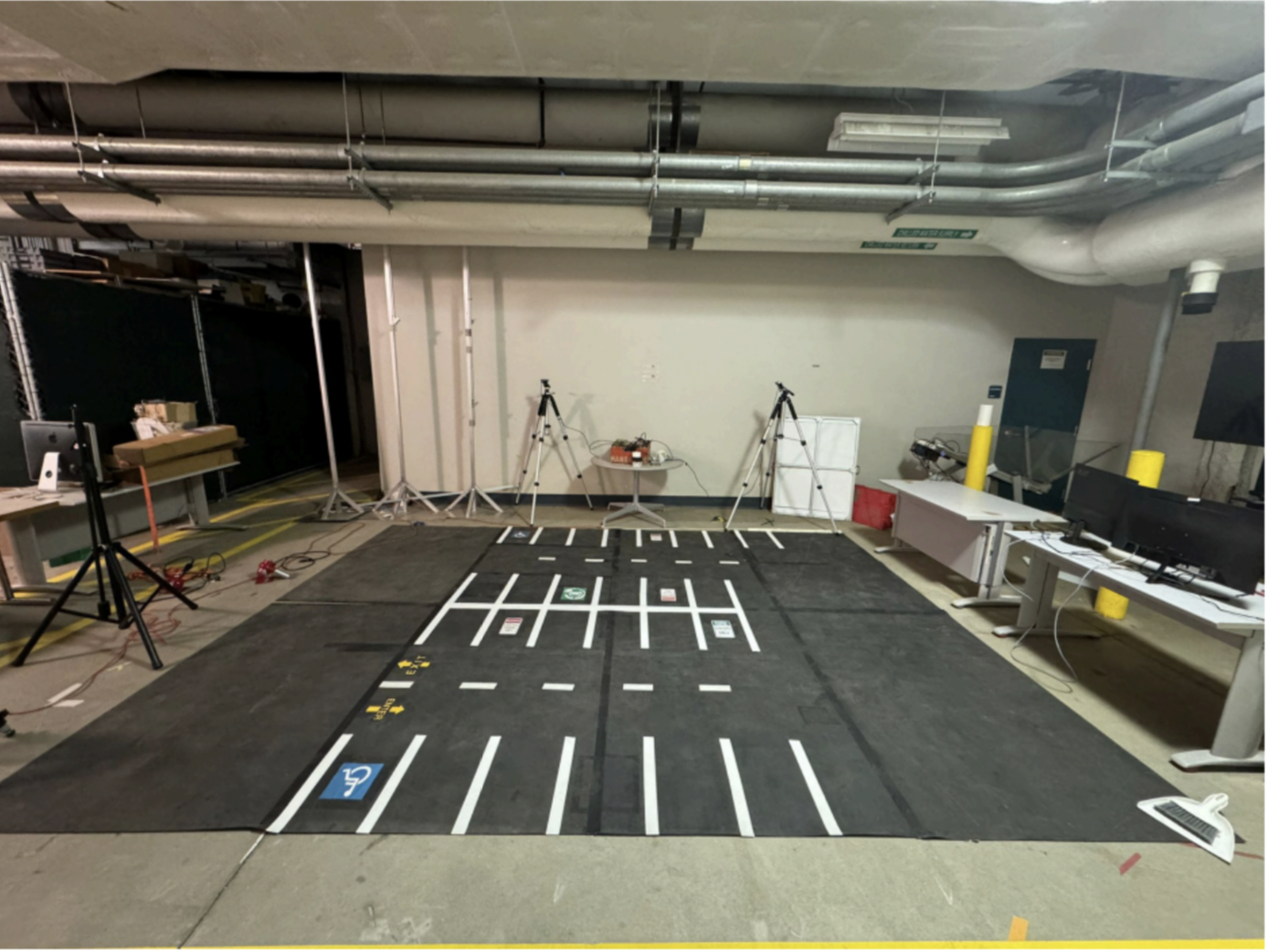
- Creating a miniature setup to mimic scenario of a parking lot
- The setup allows testing forward, backward, and parallel parking scenarios
PERCIV mostly relies on external sensing for teleoperation of RC cars in the miniaturized parking lot scenario. Currently, the external sensing involves using RGB cameras which will be expanded to incorporate depth sensing to output point clouds of the environment. Some data from onboard sensors are also used. This involves reading odometry data for estimating the position of the car and proximity sensors for estimating nearby obstacles. The onboard data is transmitted wirelessly to a computer through a ROS2 DDS node communication. External sensors are connected to the local network over a wired connection and transmitted to a control module (computer).
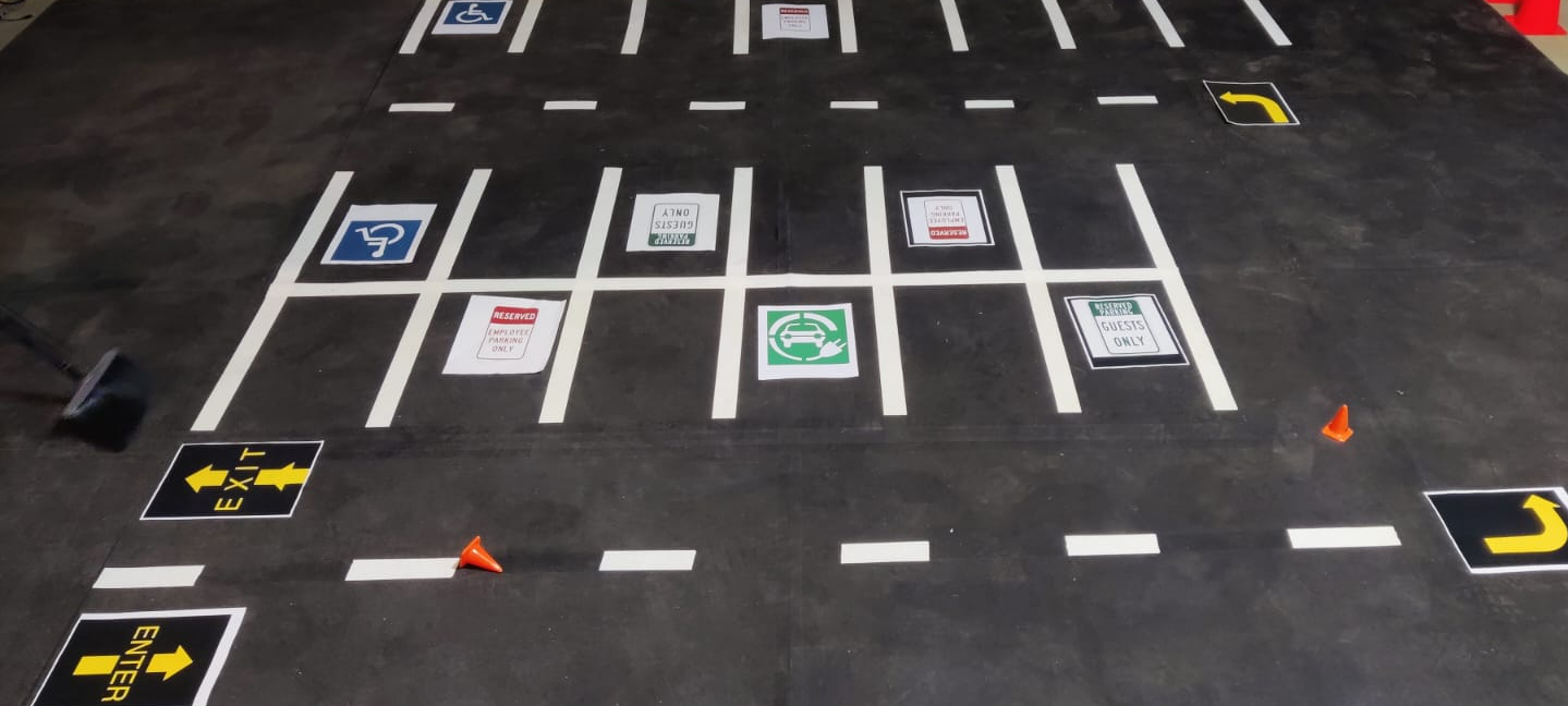
Figure 1. PERCIV Environment setup
Hardware Setup:
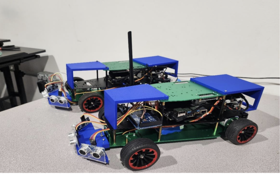
- ROSMASTER R2 is a mobile car with Ackerman steering structure developed based on ROS system.
- Ultrasonic sensors are mounted for collision detection and safety pipeline.
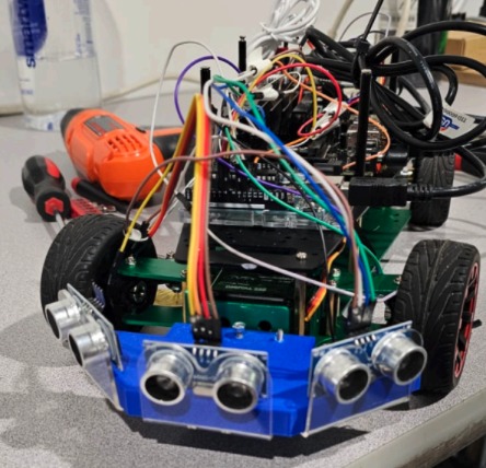
Figure 2. PERCIV Jetacker Car
Perception Subsystem:
Currently the perception pipeline consists of the following flow:
- Receive time-synchronized image frames from the intel Realsense using software implementation of GenLock, in which a trigger is sent programmatically to the realsense sensors to control the shutters and exposures.
- Once the time-synchronized images are received, they are stitched using a Graph-Neural Network based stitcher optimized to run in realtime and to operate in feature sparse environments.
- Once the scene is stitched, points are selected manually to perform perspective transform into a BEV. Inverse Perspective Mapping was also experimented, but due to better fidelity of a simple homography using perspective transformation in our case we decided to stick with perspective transforms. The final stitched BEV can be seen in Figure 3.
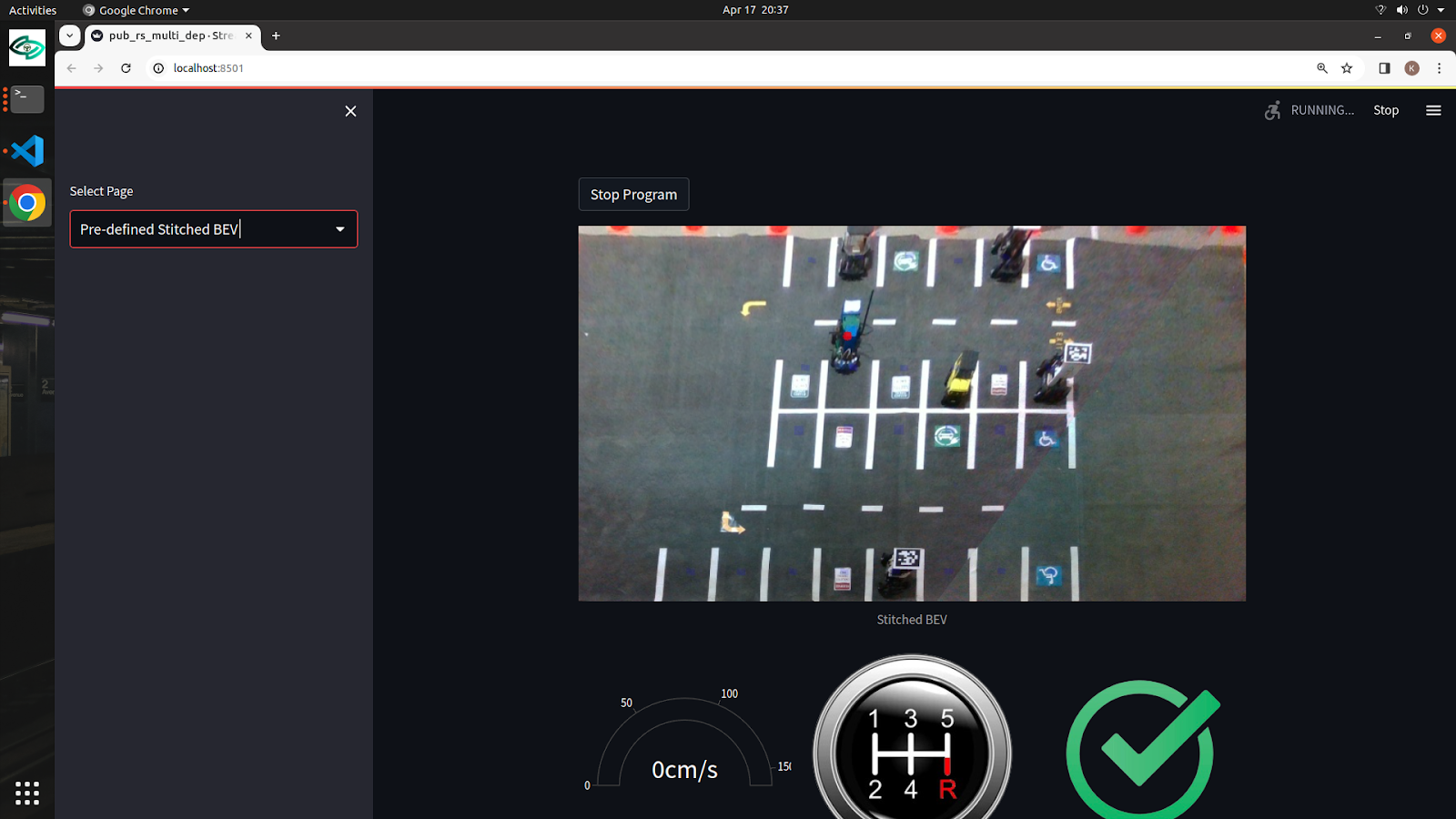
Figure 3. Stitched BEV output
- With the BEV generated a learning-based algorithm is used for keypoint detection for explicitly pose estimation of the ego-vehicle. The mAP (mean average precision) we were getting against the ground-truth (measure using an ArUCO marker) was 97.5%. The estimated pose can be seen in Figure 4:

Figure 4: Estimated pose estimation for the ego-vehicle
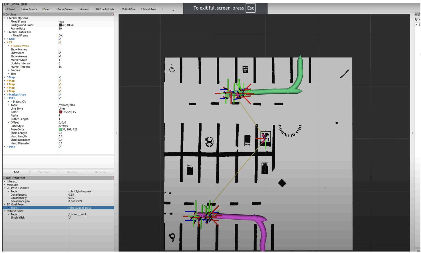
- With the pose of the ego-vehicle determined the kinodynamic model is used complemented by the user input to generate trajectories as a t+nth timestep based on the ackermann steering. The predicted trajectories in green can be seen in Figure 5 below:

Figure 5: Predicted trajectories using estimated pose and controller input
- Finally an independent greedy-heuristic for box-to-box center alignment and pose alignment to detect successful parking. Figure 6 depicts the translucent green overlay achieved as a result of successful parking:

Figure 6: Green overlay depicting successful parking and within the designated tolerance
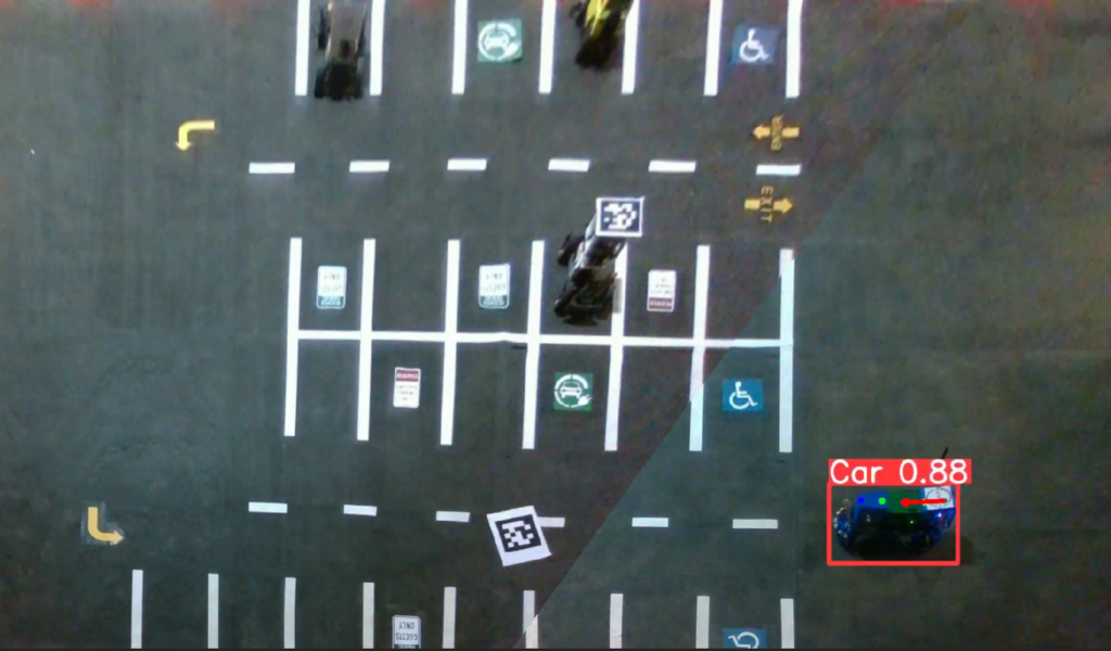
Figure 7: Pose estimation of the car in the PERCIV environment
Controls Subsystem:
- Steering and Throttle Input: For our setup, we used the Logitech G29 steering and pedal setup. We fine-tuned the force feedback steering option to replicate the sensation of maneuvering a real vehicle, ensuring an immersive driving experience. The pedal shifters integrated into the steering wheel offer gear changes, allowing drivers to transition through three forward gears and one reverse gear, which is also displayed on the UI/UX. The plus-minus button on the wheel can be used to change the length of the trajectory prediction. The red button can be used to disable the safety checking vehicle driving the car.
- Trajectory prediction: Trajectory prediction stands as a pivotal feature, offering drivers a proactive understanding of the vehicle’s forthcoming position based on present throttle and steering inputs. This tool enhances situational awareness, allowing drivers with foresight to navigate with precision and confidence. Because we are using an Ackerman type of car, we used the peppy model to predict car position and orientation given the steering commands. The lookahead distance was based on the length that the driver selected using the plus-minus button on the steering.
- Collision Avoidance: In order to mimic the actual car, we had 3 sensors in the front and 1 sensor in the back, as shown in figure 8. These were low-cost proximity sensors and a very narrow FOV of 5 degrees. The logic involved reading these ultrasound sensor data topics, as well as the teleoperation setup input data topic (raw_cmd_vel) to filter out unsafe command velocity components and only publish velocities that are safe to execute (do not move the car in the direction of possible collisions). Therefore, these safe velocities are published in a ROS topic (cmd_vel). These safe velocities are then subscribed directly to the car and executed.
- Offering a range of functionalities to control the car includes managing gear shifts, steering, and pedals, as well as processing user input to navigate the vehicle within the environment.
- Future works includes incorporating cruise control and navigation using waypoints.

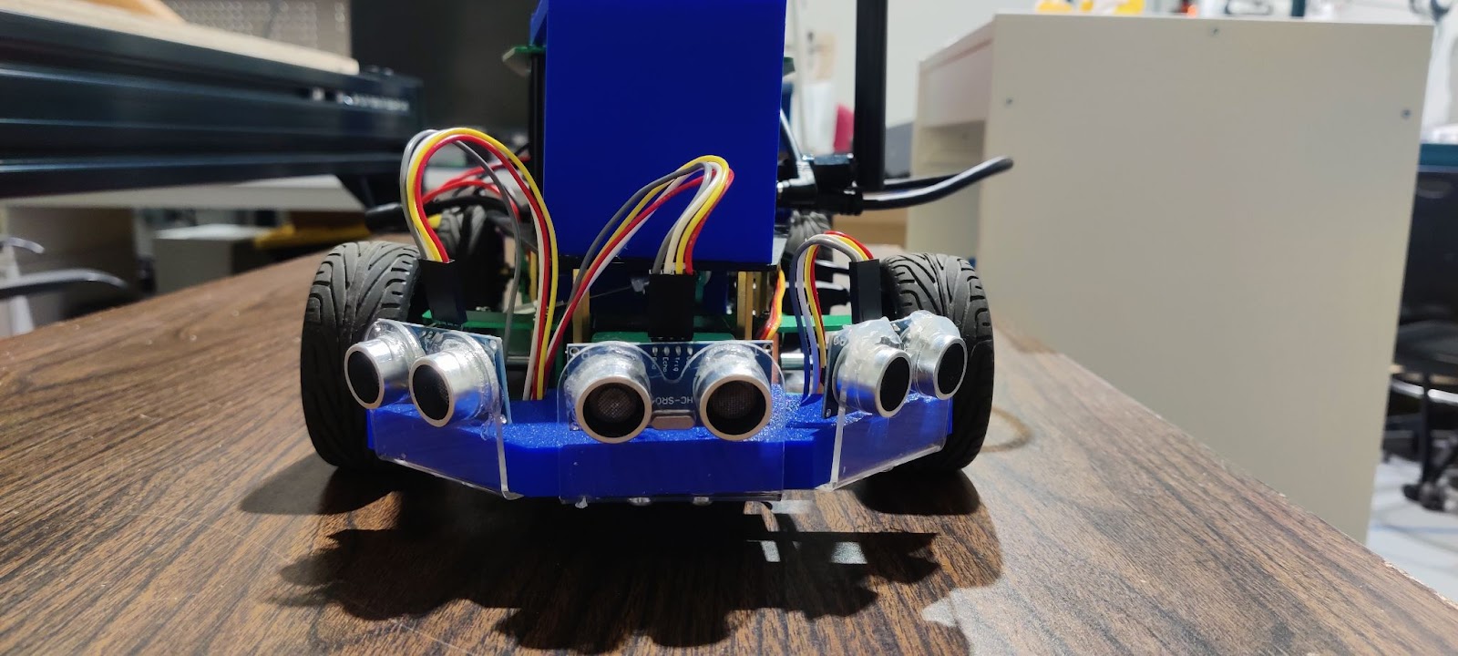
Figure 8: Sensor placement on the car
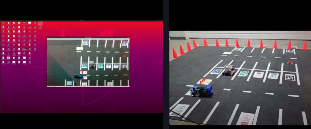

Figure 9: Demonstration of Trajectory prediction based on steering configuration
UI/UX:
Inherently, the complete system is a human-machine interface with UI/UX as a core submodule of the complete system. Various off-the-shelf solutions which included ROS web-bridge integration with bootstrap, Glovo, and simple HTML CSS based designs, but due to limited flexibility to change the UI/UX and high latency/low throughput from the web-bridge we opted to design our custom UI/UX design using StreamLit and ReactJS. The communication between the frontend and backend was achieved using ROS topics with high compression rates for image frames for high throughput. The elements included a side navigation bar for selecting between raw CCTV footage, pre-defined parameters for stitched BEV, and user-defined parameters for stitched BEV. In addition, the user was provided with a real time feed of the environment bolstered by other graphical interfaces which included a speedometer, gear status, and safety override status. Figure 12 shows the current status of our UI/UX:
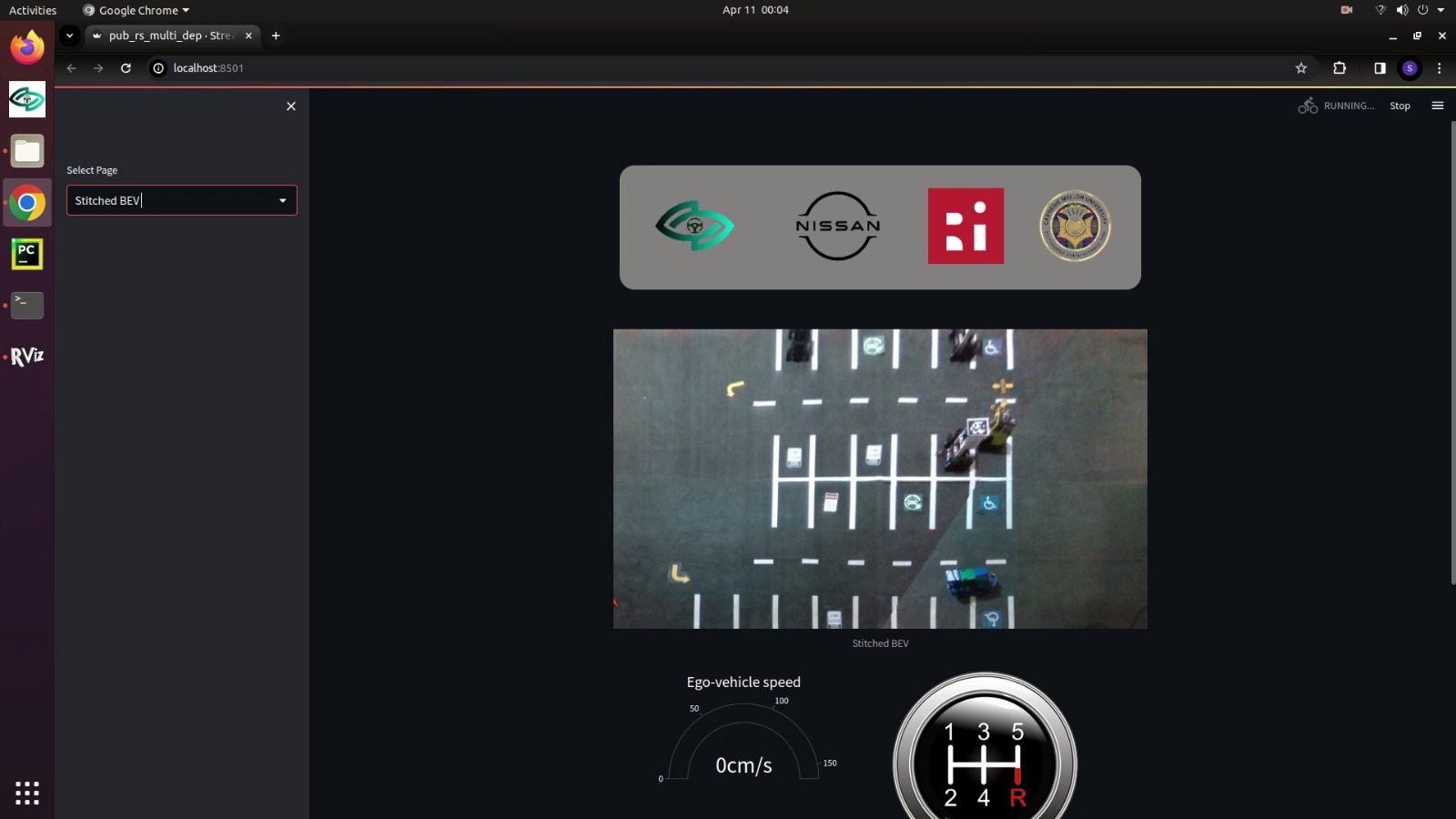
Figure 10: UI/UX depicting stitched BEV, speedometer, gear status, and safety override status
- Multiple Visualization Views: Offering diverse visualizations for enhanced understanding.
- Integration of Control and Perception Data: Displaying data from both control and perception layers for comprehensive insight.
- Bird’s Eye View (BEV) Display: Presenting a BEV of the environment for improved spatial awareness.
- Predicted Trajectory Visualization: Displaying predicted trajectories of the car to aid in navigation.
- Real-Time Indicators: Providing real-time indicators such as current speed, collision alerts, and corridor breach alerts for situational awareness.
Final System Implementation
Mechanical/Environmental Subsystem:
The mechanical/environmental subsystem establishes the physical test setting. It includes a modular test track, camera mounting infrastructure, and calibration markers, all scaled to represent a simplified parking lot scenario suitable for our 1/10th scale RC car platform. The scaled version of the environment can be seen in Figure 8 below.
Test Track Setup: The track is assembled from interlocking floor panels placed on a flat surface. Lane markings and parking spot outlines are applied with white tape or paint, providing high contrast against the black-carpeted surface. This ensures reliable visual cues for the overhead cameras to detect and aids in achieving consistent traction for the RC car’s tires. The lane geometry allows the car to navigate turns and parking maneuvers in a manner consistent with the project’s requirements.
Camera Mounting: Four overhead RGB cameras are mounted on stable tripods at the corners or edges of the track. Their fields of view overlap sufficiently to produce a stitched bird’s-eye-view (BEV). By carefully positioning these cameras, we ensure that no significant areas of the track are occluded and that parking spots, lane boundaries, and calibration markers remain visible.
ArUco Calibration Markers: ArUco markers are placed at known positions on the track to facilitate camera extrinsic calibration and alignment. These markers provide fixed references, enabling the perception subsystem to transform raw camera images into a consistent coordinate frame.
RC Car Platform and Onboard Components:
The chosen RC car features an independent suspension system and a rear-wheel drive, powered by a brushed DC motor. Steering is accomplished via a standard hobby-grade servo controlling the front wheels, providing smooth and proportional angle adjustments. When placed on the prepared track, the car’s turning radius, tire traction, and suspension characteristics meet the requirements for both careful teleoperation maneuvers and more dynamic navigation commands issued by an autonomous local planner. Within the car’s body shell, a compact microcontroller board interprets incoming commands and provides feedback. The complete assembly of the RC car can be seen in figure 9 below. The key onboard electronic elements are:
- Steering Servo: Adjusts the front wheels’ angle. In teleoperation mode, the servo reacts directly to the operator’s steering commands. In autonomous mode, it executes steering angles computed by the planner’s path-following algorithms.
- Wireless Module: Enables bidirectional communication with the offboard compute. During teleoperation, steering and speed commands originate from the operator’s UI; for autonomous mode, the offboard node sends trajectory commands and possibly corrective updates. The wireless link also returns telemetry data—such as basic odometry and proximity sensor readings—to the offboard system.
- Ultrasonic Proximity Sensors: Mounted at the car’s front, these sensors detect nearby obstacles at close range. If the operator attempts a risky maneuver or if the autonomous planner’s intended action would lead to a collision, these readings inform the offboard logic to override commands and prevent unsafe motion.
Sensing, Localization, and Communication Subsystem:
Currently the perception pipeline consists of the following flow:
- Receive time-synchronized rgb image and depth frames from the intel Realsense using software implementation of GenLock, in which a trigger is sent programmatically to the realsense sensors to control the shutters and exposures.
- Once the time-synchronized images are received, they are stitched using a Graph-Neural Network based stitcher optimized to run in realtime and to operate in feature sparse environments.
- Once the scene is stitched, points are selected manually to perform perspective transform into a BEV. Inverse Perspective Mapping was also experimented, but due to better fidelity of a simple homography using perspective transformation in our case we decided to stick with perspective transforms. The final stitched BEV can be seen in Figure 11.
- With the BEV generated a learning-based algorithm is used for keypoint detection for explicitly pose estimation of the ego-vehicle. The mAP (mean average precision) we were getting against the ground-truth (measure using an ArUCO marker) was 97.5%. The estimated pose can be seen in Figure 11.
- With the pose of the ego-vehicle determined the kinodynamic model is used complemented by the user input to generate trajectories as a t+nth timestep based on the ackermann steering. The predicted trajectories in green can be seen in Figure 11.
- Finally an independent greedy-heuristic for box-to-box center alignment and pose alignment to detect successful parking. Figure 11 depicts the translucent green overlay achieved as a result of successful parking:
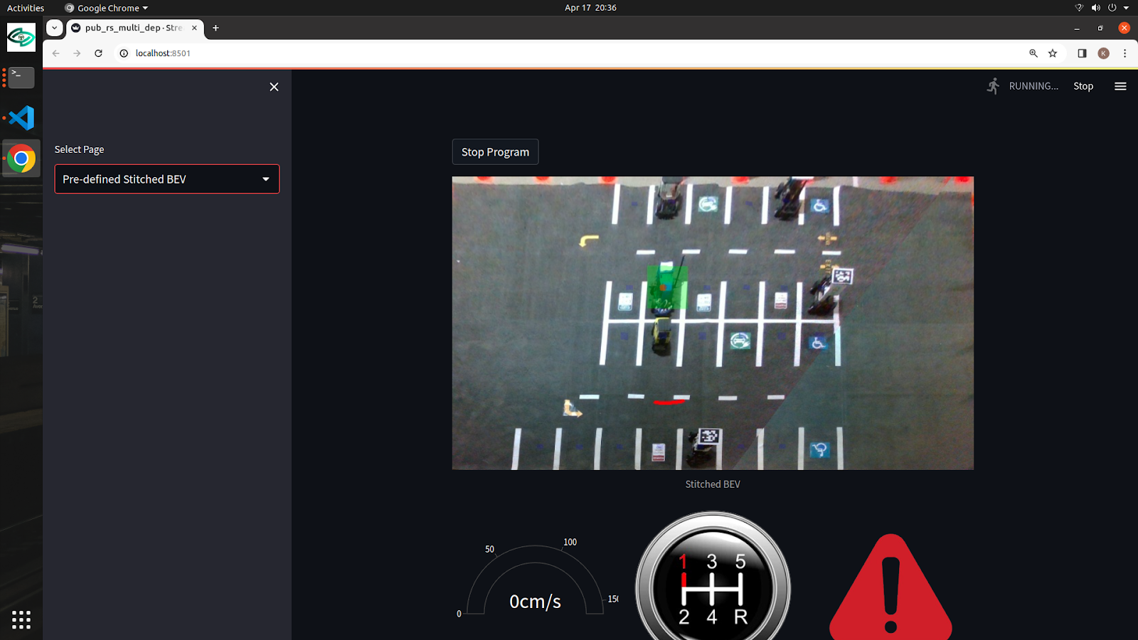
UI/UX:
Inherently, the complete system is a human-machine interface with UI/UX as a core submodule of the complete system. Various off-the-shelf solutions which included ROS web-bridge integration with bootstrap, Glovo, and simple HTML CSS based designs, but due to limited flexibility to change the UI/UX and high latency/low throughput from the web-bridge we opted to design our custom UI/UX design using StreamLit and ReactJS. The communication between the frontend and backend was achieved using ROS topics with high compression rates for image frames for high throughput. The elements included a side navigation bar for selecting between raw CCTV footage and pre-defined parameters for stitched BEV with multi-fleet car control. In addition, the user was provided with a real time feed of the environment bolstered by other graphical interfaces which included a speedometer, gear status, and safety override status.
Planning and Control Subsystem:
The planning and control subsystem is responsible for translating high-level inputs—either direct operator commands in teleoperation mode or autonomous navigation goals from the planner—into smooth and precise vehicle motion. It ensures that the RC car follows desired trajectories, maintains speed constraints, and respects safety requirements in both operational modes.
In teleoperation mode, the operator provides continuous steering and throttle inputs via the user interface. These inputs are relayed to the offboard compute, where they are subject to basic safety checks. After passing these checks, the commands are forwarded to the car’s low-level control loops. The steering servo adjusts the front wheels’ angle in real time as the operator turns the virtual steering wheel, and the electronic speed controller modulates the motor’s power based on the operator’s throttle input. This direct, human-in-the-loop approach offers intuitive and responsive control, allowing the operator to negotiate tight parking maneuvers or adjust speed on the fly.
In autonomous mode, the system uses a local planner running on the offboard compute to generate short-range trajectories based on waypoints or goals provided by the operator. The local planner considers the car’s current position, track boundaries, and known obstacles. It outputs a series of reference poses and velocities that smoothly guide the car from its current location to the target. The control subsystem then executes these plans by continuously calculating the appropriate steering angles and throttle commands to follow the reference trajectory. The planner can also modify the trajectory in response to new sensor data, ensuring adaptability as environmental conditions change.
At all times—whether in teleoperation or autonomous mode—the subsystem incorporates proximity sensor feedback and perception-based obstacle detection to prevent unsafe actions. If the operator tries to drive into a wall or the autonomous planner inadvertently guides the car too close to an obstacle, the control subsystem can override the command, reducing speed to zero or adjusting steering angles to avoid collisions. These overrides ensure that the system never compromises on safety, even if upstream components present risky instructions.