

System Requirements
Functional Requirements
| Functional Requirements | Performance metrics |
| Create a virtual environment | PR1 |
| Localize the vehicle in the virtual environment | PR2, PR3 |
| Identify and alert/override instructions safety issues | PR5 |
| Drive the car using external commands | PR2, PR4, PR5 |
| Park the car within a given tolerance | PR5 |
Mandatory Performance Requirements
| S. No | Performance Metrics |
| PR1 | Update frequency will be 10 Hz |
| PR2 | In motion tolerance: Translational 10 cm and Rotational: 15 Degrees |
| PR3 | Stationary tolerance: Translational 7 cm and Rotational: 10 Degrees |
| PR4 | Vehicle speed will be 10 cm/s |
| PR5 | Safety tolerance: maintain 10 cm from obstacles |
Desired Performance Requirements
| S. No | Performance Metrics |
| PR6 | Update frequency will be 20 Hz |
| PR7 | In motion tolerance: Translational 8 cm and Rotational: 12 Degrees |
| PR8 | Stationary tolerance: Translational 5 cm and Rotational: 8 Degrees |
| PR9 | Vehicle speed will be 15 cm/s |
| PR10 | Safety tolerance: maintain 5 cm from obstacles |
NOn-functional Requirements
| S. No | Non-Functional Requirements |
| NFR1 | Infrastructure cameras placed at oblique angles |
| NFR2 | Infrastructure Lidar |
| NFR3 | Onboard odometry |
| NFR4 | Onboard proximity sensors |
| NFR5 | Car Scale: 1/10th of real world |
| NFR6 | Forward Parking |
| NFR7 | Backward Parking |
| NFR8 | Parallel Parking |
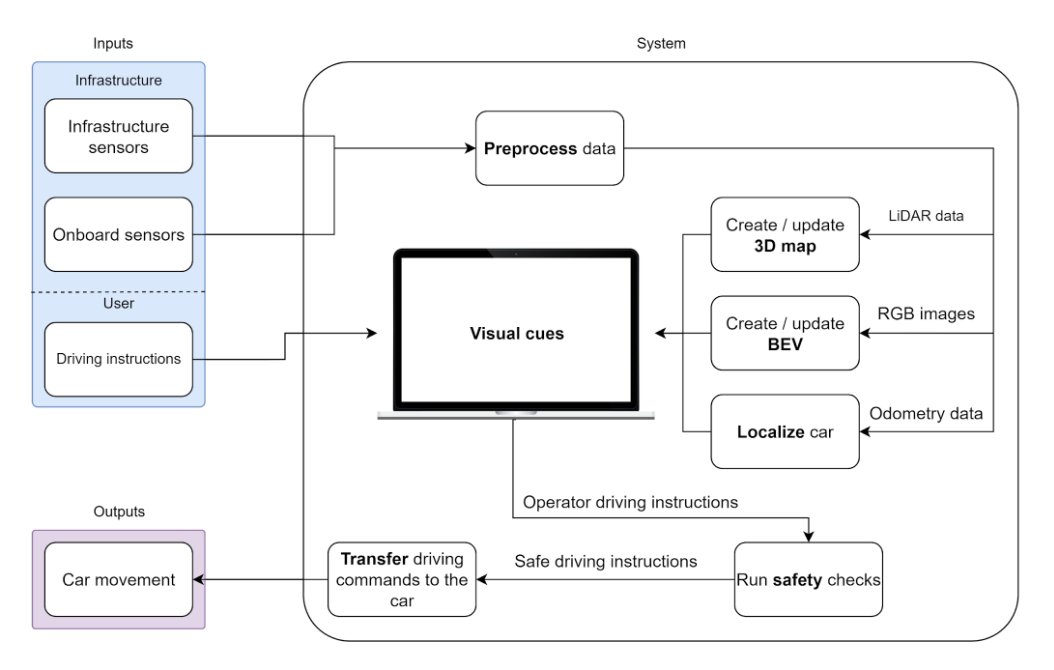
Functional Architecture
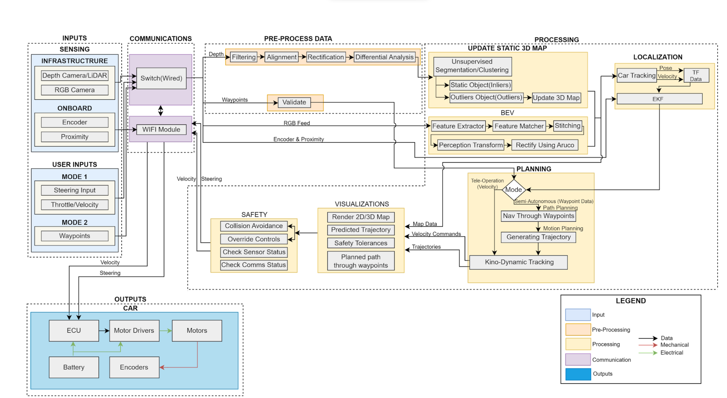
Cyberphysical Architecture
System Design Depiction
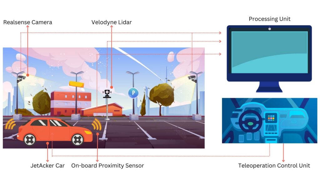
Fig1. PERCIV Environment Setup
System Components:
Our system is designed for the precise teleoperation of vehicles in parking environments, leveraging exclusively external sensing modalities without relying on any onboard perception system. The schematic representation illustrates a comprehensive approach to teleoperation, combining advanced sensor technologies with a sophisticated processing unit to enable seamless remote vehicle control.
- Sensors:
- RealSense Cameras: Placed strategically in the parking lot, these cameras capture visual data of the environment.
- Lidar Sensors: Deployed for three-dimensional mapping, Lidar sensors enhance the system’s perception capabilities by providing detailed point cloud information.
- Processing Unit:
- The processing unit serves as the central hub for data fusion and analysis. It receives inputs from RGB cameras and Lidar sensors, processing the collected information to generate a comprehensive representation of the parking environment.
- Operator Interface:
- The operator interacts with the system through a user-friendly interface, receiving real-time visual cues based on the processed sensor data. This interface provides the necessary information for precise decision-making during the teleoperation process.
- Teleoperation Commands:
- The operator, equipped with the processed environmental information, remotely controls the vehicle by providing driving instructions through the interface. These instructions are transmitted securely to the vehicle through a reliable communication channel.
Information Flow:
- Dotted lines depict the flow of data from sensors to the processing unit, highlighting the continuous exchange of environmental information.
- Solid lines represent the transmission of teleoperation commands from the operator to the vehicle, ensuring a responsive and accurate execution of driving instructions.
This integrated system not only relies on cutting-edge sensing technologies but also prioritizes a seamless communication flow between the operator and the vehicle. By removing the dependence on onboard perception systems, our teleoperation solution enhances flexibility and adaptability, making it a robust choice for precise vehicle control in parking scenarios.
Sub-System Description
Sensing Modalities:
PERCIV mostly relies on external sensing for teleoperation of RC cars in the
miniaturized parking lot scenario. External sensing involves using RGB cameras and LiDAR sensing. Some data from onboard sensors are also used. This involves reading odometry data for estimating the position of the car and proximity sensors for estimating nearby obstacles. The onboard data is transmitted wirelessly to a computer. External sensors are connected to the local
network over a wired connection and transmitted to a computer. Following data acquisition, we have a comprehensive perception pipeline. This advanced system takes the pre-processed data to generate detailed environmental representations. It creates both a 3D map and a 2D BEV spatial context in which the vehicle operates, helping in navigation and obstacle avoidance. Our teleoperation system’s efficacy depends on generating a dense and accurate 3D point cloud map. We evaluated four perception sensors – Velodyne Lidar, Zed Camera, Kinect V2, and Intel RealSense – focusing on dense point cloud creation, short-range accuracy (5-10m), and overall suitability. Based on the trade study outcomes, our project will utilize the Intel RealSense camera and Velodyne 16 Lidar sensor for the generation of 2D bird’s-eye-view (BEV) and 3D maps, respectively, encompassing the entire environment.
UI/UX Pipeline:
The generated maps are then integrated into our UI/UX pipeline. Here, visual cues are overlaid on the maps, taking into account the data from on-board sensors and inputs from the teleoperator. This step is critical in visualizing the vehicle’s environment in a way that is intuitive and informative for the teleoperator. It helps in making informed decisions regarding vehicle control and navigation.
Furthermore, using steering inputs provided by a user, PERCIV predicts the trajectory of the teleoperated vehicle and overlays these trajectories with the 3D map. These predictions will help a user with more intuitive control of a remote vehicle, in a similar fashion to the reverse parking cameras, especially when maneuvering a vehicle in tighter spaces. Additionally data from onboard odometry and proximity sensors to create safe distance overlays on the 3D map. These safety distances will help a user safely navigate a complex environment. Braking distance will show how far a vehicle might travel before coming to a stop.
Collision warning distance will be used to trigger warnings to a user about potential collisions. A visualization of safe distances is indicated in Figures 2 and 3.

Fig 2. Possible options for safety distances that can be incorporated in PERCIV

Fig 3. Safety distances visualized in a 3D map like scenario
RC Car:
For our project, demonstrating a Proof of Concept using a scaled-down model requires understanding the concept of ‘scale’ in RC vehicles. Scale represents the reduction ratio from a real car to an RC model, with common scales being 1/24, 1/18, 1/12, 1/10. The track for our project, modeled after a real-world track, will have a lane width about twice that of the car width. This means the RC vehicle’s size directly influences track design, balancing the need for a manageable track size against the feasibility of customization and component mounting on
smaller models. We evaluated the performance of four RC cars: Latarax Prerunner, Horizon Axial, Traxxas XL-5 and JetAcker. The comprehensive trade study highlights JetAcker as the best choice for the basis of this subsystem. The JetAcker is a 1/10 scale RC vehicle equipped with Ackermann steering, features a 3D depth camera and Lidar for remote communication and precise mapping. Its robust 11.1V 6000mAh lithium battery ensures enduring performance. The platform supports Ubuntu and ROS1 making it an advanced choice for research and applications.
Planning and Control:
The planning and control subsystem will involve three major components–steering and throttle control, motion planning, and path planning. PERCIV has two modes of operation–mode:
1: Steering and throttle control and mode
2: Waypoint input.
For the first mode, the user can control the vehicle continuously by providing steering and throttle inputs. These inputs will be received via a gaming steering wheel and pedals. For mode 2 operation is a semi-assisted mode of operation where a user doesn’t need to control the vehicle continuously. Instead, a user can just select waypoints on the 3D map which will be followed by the vehicle. Control signals for the car will be generated by an external computer and only the final control signals will be transferred to the vehicle.