Requirements
Performance Requirements
| Requirement # | Requirement | Target |
| M.P.1 | From bone STL to physical bone registration | < 5mm RMSE |
| M.P.2 | End-to-end bone tracking latency | <= 500 ms |
| M.P.3 | Tracked bone pose jitter | <= 3 mm, 3 deg RMSE |
| M.P.4 | End-to-end controller-to-robot latency | <= 750 ms |
| M.P.5 | End effector autonomous force | < 50 N |
| M.P.6 | End effector lateral error from guide line | <= 3mm RMS, 3mm maximum |
| M.P.7 | End effector axis-angular error from guide line | <= 3 deg |
| M.P.8 | Starting pose in selected guide accuracy | <= 5 mm, 3 deg |
| M.P.9 | Tool tip accuracy on bone (SVD) | <= 4 mm |
| M.P.10 | Success rate with full requirements | >= 4/5 trials |
| M.P.11 | Guide deviation prevention rate | 10/10 trials |
| M.P.12 | E-stop pressed latency to full stop | <= 250 ms |
| M.P.13 | Time to stop after tracking loss | <= 250 ms |
| M.P.14 | Visual Registration succeeds across diverse color tones and lighting intensities | >= 90% of samples |
| M.P.15 | Point cloud registration succeeds with bones displaced by ±15 degrees or ±10 cm | >= 80% of trials |
| M.P.16 | Final registration accuracy under all operating conditions | Within +- 5mm |
| M.P.17 | Motion-to-motion latency in Augmented Reality (AR) | < 300 ms |
| M.P.18 | Live camera feed acquisition rate | > 10 fps |
| M.P.19 | Bone markings identification resolution | <= 1mm diameter |
Functional Requirements
- FR-01: Accept pre-operative CT scan as a 3D reference frame for surgical planning.
- FR-02: Continuously detect + track 6-DOF pose of surgical tools and anatomical reference markers.
- FR-03: Register the CT coordinate frame to physical patient anatomy in real time using IR data.
- FR-04: Render and display a surgical-plan overlay (drill sites, cutting planes) aligned to scene.
- FR-05: Enable a remote surgeon to select drill axis, plane, depth and transmit commands to robot.
- FR-06: Navigate the KUKA LBR Med 7 to the planned drill pose and execute drilling or cutting.
- FR-07: Block out-of-bound commands; detect aggressive bone motion; provide E-stop capability.
- FR-08: Allow the surgeon to pause, abort, or manually override robot motion at any point.
- FR-09: Surgeon commands shall be constrained within the pre-op plan envelope; enforced by software geofence.
Non-Functional Requirements
- NFR-01: End-to-end control latency ≤ 100 ms (stretch).
- NFR-03: Continuous operation up to 4 h without restart.
- NFR-04: AR rendering ≥ 30 FPS.
- NFR-05: IEC 62304 + ISO 10218 compliance.
- NFR-06: Patient data encrypted per HIPAA.
- NFR-07: Graceful degradation with surgeon override.
Functional Architecture
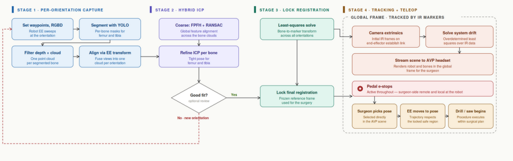
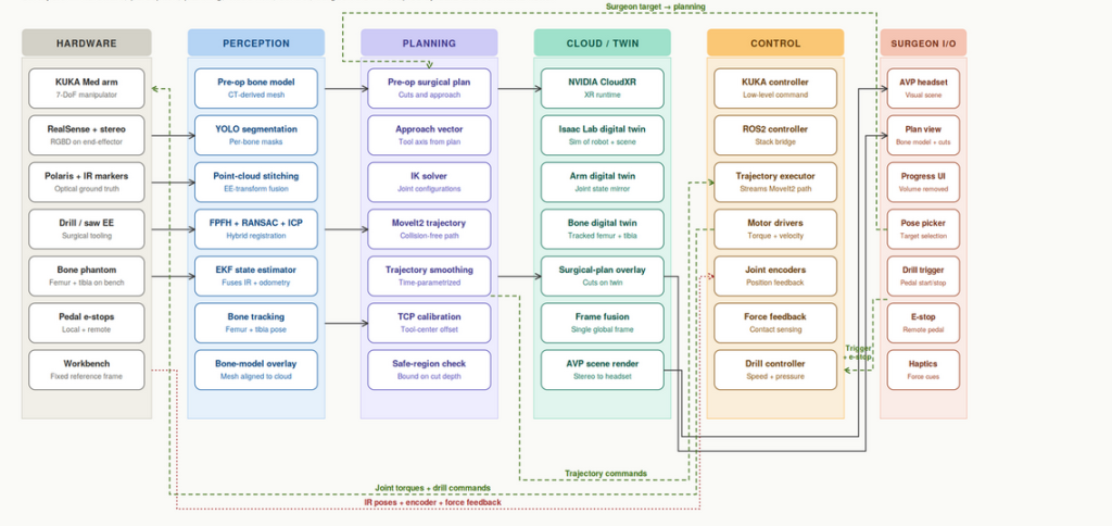
Cyberphysical Architecture
Design Description
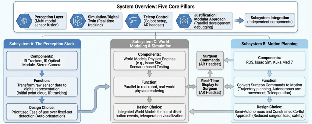
System Overview: The system integrates five core pillars identified in the research:
- Perception Layer: Multi-modal sensor fusion (IR tracker/Stereo Camera) for environment modeling and tracking.
- Simulation/Digital Twin: A continuous loop with real-time tracking to display all changes and actions to the doctor.
- Teleop Control: A co-bot setup where al invasive procedures are teleoperate by the surgeon from the AR headset and other rudimentary motions are automated to make procedure a lot more smoother
Justification: This modular approach allows for better debugging and parallel development since all components can be worked on independently.
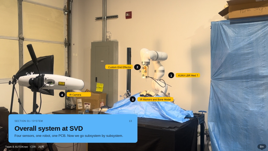
Subsystem Descriptions
Subsystem A: The Perception Stack
This subsystem transforms raw sensor data into a structured digital representation of the factory floor.
- Components: IR Trackers, IR Optical module, Stereo Camera.
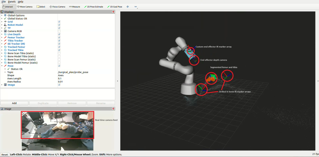
- Function: It utilizes Stereo camera to get the initial point cloud and position of markers with respect to the bone attached. One we have the relative position we can begin with IR tracking of the bone.
- Design Choice: We prioritized Ease of use for end-user over fixed-set detection to allow the robot to identify the correct orientation instead of a human manually registering and calibrating it.
Subsystem B: Motion Planning
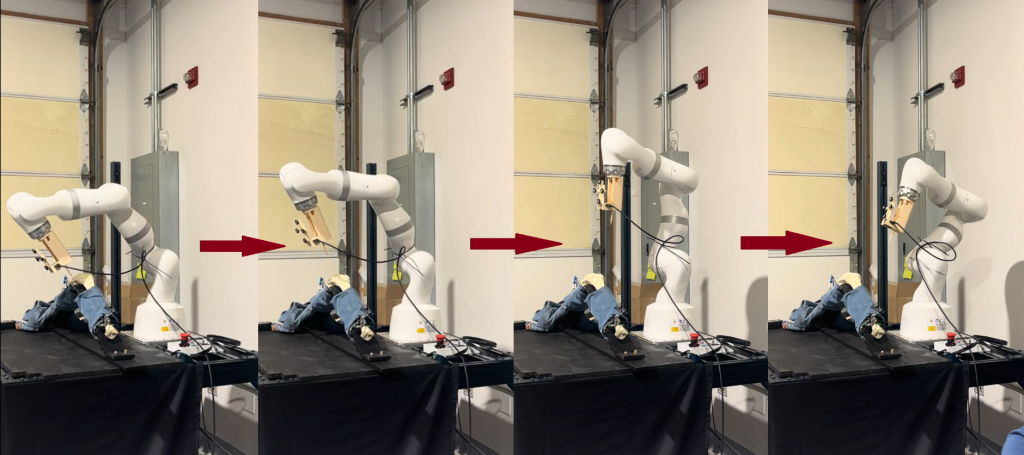
This section converts the commands from Surgeon into motion. For example surgeon select a line to drill along ,this section will plan the trajectory for the whole driving procedure and autonomously move the arm to the starting location of the line in 3d space and after that surgeon teleoperate it.
- Components: ROS, Isaac Sim, Kuka Med 7.
- Function: Plan the trajectory for the whole given procedure and autonomously move the arm to the starting location of any procedure and then translate surgeons command into motion.
- Design Choice: Earlier we planned to do everything autonomously but that approach was discarded since it could have been very tiring for the doctor and if even by mistake the doctor moved his/her in simulation abruptly it would have caused the actual robot arm to go berserk. Instead, we utilize Semi Autonomous and constrained Co-Bot approach to keep the load as low as possible on the doctor and prevent mishaps.
Subsystem C: World Modeling & Simulation
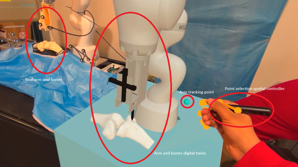
This subsystem acts as the “imagination” of the robot, transferring everything from the robot to the Apple Vision Pro.
- Components: World Models, Physics Engines (e.g., Isaac Sim), and Scenario-based Testing suites.
- Function: It runs parallel to the real robot, rendering everything in real world physics.
- Design Choice: We integrated World Models to better account for “out-of-distribution” events and ease of teleoperation visualisation and controls.
Design Alternatives and Trade-offs
| Alternative | Status | Reason for Rejection |
| End-to-End Teleop Control | Discarded | Safety/Reliability: Tiring and can cause mishaps . |
| Manual Registration | Discarded | Erroneous: Manual point marking on bone from intuition can introduce more errors. |
| Stereo-Only Tracking | Discarded | Information Loss: Less accurate, works good only at close distance and readings drift over time |