
System Requirements
| Performance Requirements | |||
| ID (Functional) | Functional Requirement | ID (Performance) | Performance Metric |
| MF1 | The system shall sense the surrounding environment. | MP1 | Sense the environment within the range of 0.5–4 m from the Flying Hand |
| MF2 | The system shall localize its own pose relative to the environment. | MP2 | Localize position with an error of at most 5 cm under nominal conditions |
| MF3 | The system shall allow an operator to manually pilot the Flying Hand to an Area of Interest (AOI). | MP3 | Navigate at speeds up to 1 m/s during manual flight |
| MF4 | The system shall allow the operator to define a Point of Interest (POI) from the video feed. | MP4 | Detect a POI from a distance of at least 0.6 m |
| MF5 | The system shall manipulate the end-effector to establish contact with the POI. | MP5 | Maintain end-effector positioning accuracy within ±0.5 m during contact-based NDT |
| MF6 | The system shall maintain stable end-effector contact during NDT execution. | MP6 | Maintain stable contact under wind disturbances up to 3 m/s |
| MF7 | The system shall perform contact-based non-destructive testing. | MP7 | Complete at least 5 NDT measurements in a single flight |
| MF8 | The system shall store and relay NDT data to the ground station. | MP8 | Relay data to the ground station with latency not exceeding 100 ms |
| MF9 | The system shall execute a fail-safe response upon loss of communication. | MP9 | Execute a fail-safe response within 1 s of communication loss |
| MF10 | The system shall provide real-time visual feedback to the operator. | MP10 | Video delay within 110-200ms |
| MF11 | The system shall autonomously plan arm motion to reach a selected POI. | ||
| Non-functional Requirements | |
| ID | Description |
| MN1 | The system shall be modular to allow rapid probe or end-effector replacement. |
| MN2 | The total take-off mass shall not exceed 15 kg. |
| MN3 | The system shall be operable by a trained operator with minimal setup time. |
| MN4 | The system shall store NDT data in standard reusable formats. |
| MN5 | The system shall operate in temperatures from -5°C to 40°C and humidity up to 95%. |
Functional Architecture

The functional architecture of the Flying Hand system presents the overall operational structure from system inputs to inspection outputs. The system begins with three primary inputs: a user defined Point of Interest that specifies where inspection is required, environmental conditions that influence sensing and flight performance, and electrical power that enables all onboard components to operate. These inputs support the core functional blocks of sensing, localization, navigation, manipulation, and inspection. Sensor data enables vehicle localization, allowing the navigation module to plan and execute motion toward the designated Area of Interest. During flight, the system maintains stable hover and position control to ensure safe and precise operation. Once the platform reaches the inspection region, the manipulation module positions the end effector, and the system performs Non Destructive Testing. Throughout the mission, communication modules support data exchange and supervisory control. The resulting outputs include NDT sensor measurements, drone location, end effector position, and safe return to home capability. This functional view defines what the system does and how information and control flow between major operational components, serving as a foundation for the subsequent cyberphysical architecture.
Cyberphysical Architecture
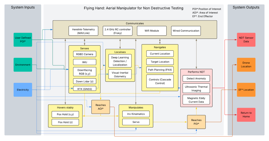
The Flying Hand system architecture integrates sensing, localization, navigation, manipulation, and inspection into a single coordinated framework designed for reliable aerial Non Destructive Testing. Multiple sensors, including RGBD cameras, an inertial measurement unit, RTK GNSS, LiDAR, and downward facing vision sensors, provide the data required for accurate state estimation in both GPS available and GPS limited environments. These inputs are processed through visual inertial odometry and learning based localization algorithms to determine the drone’s precise position and orientation. The navigation layer uses PX4 based path planning and cascade control to ensure stable flight, accurate hovering, and controlled movement toward defined Areas of Interest and Points of Interest. Once positioned, inverse kinematics and servo control guide the end effector to perform contact based inspections such as ultrasonic, thermal, and magnetic eddy current measurements. Communication interfaces, including MAVLink telemetry, radio control, WiFi, and wired connections, enable real time monitoring and data transmission. The system delivers inspection data, drone and end effector location information, and return to home capability, forming a robust and dependable aerial inspection platform.
System Design description
Sensing Subsystem
The sensing subsystem provides environmental perception and state awareness necessary for autonomous flight and inspection. The system integrates RGBD cameras, a vision sensor dedicated for visual inertial odometry, LiDAR, inertial measurement units, and RTK GNSS. This multi modal sensing architecture was selected to increase robustness and reduce failure risk in GPS limited and visually degraded environments.
The primary visual inertial odometry camera is currently mounted in a downward facing configuration. This orientation was chosen to maximize feature density from ground textures during hover and low altitude inspection operations, thereby improving estimator stability. However, the mounting orientation remains an experimental design variable. If flight experiments demonstrate that the forward scene consistently contains sufficient visual features during mission execution, the camera may be repositioned to a forward facing configuration. This alternative configuration would align more closely with standard ROS2 conventions for visual inertial odometry visualization in RVIZ, where forward motion corresponds to the optical axis of the camera.
RGBD sensing supports depth aware obstacle detection and surface mapping, which are critical for close proximity inspection tasks. LiDAR provides geometric consistency and reliable ranging in cases where visual features degrade due to lighting conditions or low texture industrial surfaces. The inertial measurement unit supplies high frequency motion updates required for stable control and tightly coupled visual inertial fusion. RTK GNSS, when available, is used to constrain long term drift during transit segments and improve global positioning accuracy.
The decision to adopt heterogeneous sensing rather than relying on a single modality was driven by mission risk analysis. Industrial inspection environments introduce lighting variability, metallic interference, occlusion, and structural complexity. A redundant perception stack significantly reduces the probability of localization failure and supports safe and reliable operation.
Localization Subsystem
The localization subsystem estimates the full six degree of freedom pose of the aerial manipulator. It fuses inertial, visual, and GNSS measurements through a visual inertial odometry pipeline augmented by learning based object localization.
Visual inertial odometry was selected over purely visual SLAM due to its improved short term accuracy and robustness during dynamic flight. The inclusion of inertial fusion reduces scale ambiguity and enhances estimator stability during aggressive maneuvers or rapid attitude corrections. GNSS measurements are incorporated when available to correct long term drift during global navigation segments.
Learning based localization modules were included to improve semantic awareness of structural features within inspection environments. This enables more reliable detection of Areas of Interest and enhances target alignment prior to manipulation.
Estimator consistency and bounded drift were primary design criteria. Inspection accuracy depends directly on pose precision, particularly during contact based measurements. A tightly coupled fusion architecture ensures that navigation and manipulation subsystems receive high confidence state estimates under varying environmental conditions.
Navigation Subsystem
The navigation subsystem is responsible for trajectory generation, path tracking, and flight stabilization. It leverages a PX4 based flight control stack with cascade control architecture.
PX4 was selected due to its reliability, modular design, and ability to support custom control extensions. The cascade control structure separates inner loop attitude stabilization from outer loop position control. This layered control approach enables stable flight while allowing higher level planners to generate mission driven trajectories.
Navigation is structured hierarchically. A global planning layer generates mission waypoints toward Areas of Interest and Points of Interest. A local planning layer refines trajectories based on real time obstacle detection and localization feedback. This structure balances computational efficiency with responsiveness to environmental uncertainty.
Precise hover performance was a key design requirement. Contact based inspection requires centimeter level stability and disturbance rejection. Controller tuning prioritizes hover stability and position holding accuracy rather than aggressive maneuverability.
Manipulation Subsystem
The manipulation subsystem controls the articulated end effector used for contact based Non Destructive Testing. It computes inverse kinematics solutions and generates servo commands to achieve the desired tool pose relative to the inspection surface.
A model based inverse kinematics approach was selected to ensure predictable and repeatable end effector motion. Manipulation introduces external forces that directly affect flight stability. Therefore, manipulator control operates in coordination with the flight controller to maintain system equilibrium during surface interaction.
Active actuation was chosen instead of passive compliance due to inspection precision requirements. Ultrasonic and eddy current sensing demand consistent contact force and surface alignment. Controlled positioning improves measurement repeatability and data quality.
The integration between navigation and manipulation subsystems represents a critical cyber physical interaction. Mechanical contact must be achieved without destabilizing the aerial platform, requiring coordinated control across both subsystems.
Inspection Subsystem
The inspection subsystem performs Non Destructive Testing once the manipulator reaches the designated Point of Interest. It supports ultrasonic imaging, thermal sensing, and magnetic eddy current measurement.
Multiple inspection modalities were selected to increase mission versatility across different materials and defect types. Ultrasonic testing enables subsurface defect detection. Thermal imaging supports detection of insulation faults and abnormal heat signatures. Eddy current sensing allows crack detection in conductive materials.
Inspection measurements are synchronized with pose estimates to enable spatially referenced defect mapping. Each data sample is timestamped and associated with precise drone and end effector position. This integration ensures traceability and supports post mission analysis.
The inspection subsystem was designed with emphasis on measurement integrity, spatial accuracy, and repeatability, as these directly determine mission value.
Communication Subsystem
The communication subsystem provides bidirectional information exchange between the aerial platform and ground control. It supports MAVLink telemetry, radio control backup, WiFi communication, and wired interfaces for high bandwidth data transfer.
Redundant communication channels were selected to reduce operational risk. Radio control provides manual override capability. MAVLink enables structured telemetry exchange between the onboard flight controller and ground station. WiFi supports transmission of high bandwidth inspection data.
The communication architecture prioritizes safety critical control signals over non essential data. This layered strategy ensures operational safety, reliable monitoring, and mission continuity.
Power Subsystem
The power subsystem distributes electrical energy to propulsion, sensing, computation, and actuation components. It includes high current distribution circuitry, voltage regulation, and real time power monitoring.
A dual battery configuration was selected to increase endurance and provide redundancy. Electrical isolation between propulsion and sensitive electronics reduces noise and improves sensor stability. Dedicated voltage regulators ensure consistent supply to compute modules and inspection sensors.
Power monitoring supports estimation of remaining flight time and triggers return to home procedures when thresholds are reached. The subsystem was designed with safety margins aligned to worst case current draw during hover with active manipulation.
Stable and predictable power delivery is essential for cyber physical reliability, as fluctuations directly impact estimator stability, communication integrity, and actuator performance.