
The Flying Hand system is organized into two primary development tracks: Prototype Subsystem (Physical System Implementation) and Simulation Subsystem (Algorithm Development + Validation):
1. Prototype Subsystem (Physical System Implementation)
This subsystem encompasses all hardware components and real-time software deployed on the physical Flying Hand platform.
1.1 Airframe Subsystem
Objective: Prepare the UAV platform for safe and repeatable flight testing.
Date: 2 April 2026
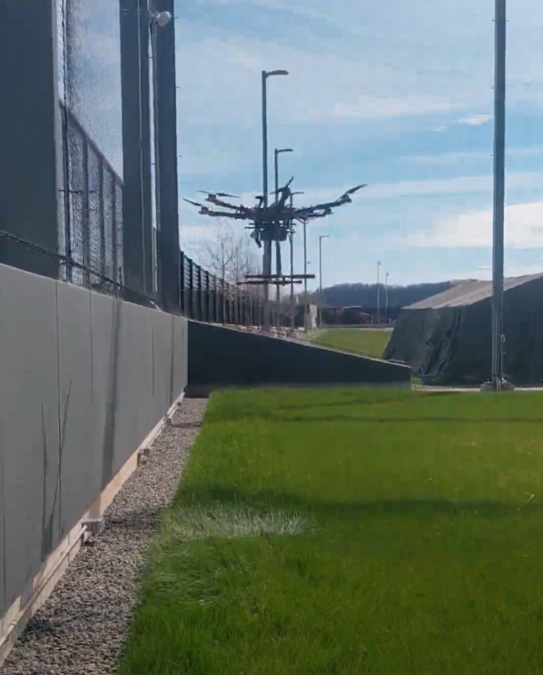
- VIO Subsystem Integrated on the UAV: VIO depth camera tilted downwards by 30 degrees to capture features from ground so as to improve position accuracy when flying close to wall/surfaces
- Further evaluated the performance of Altitude Hold and Position Hold modes under different flight conditions, and improve in-flight localization performance to support more stable flight.
Date: 18 March 2026
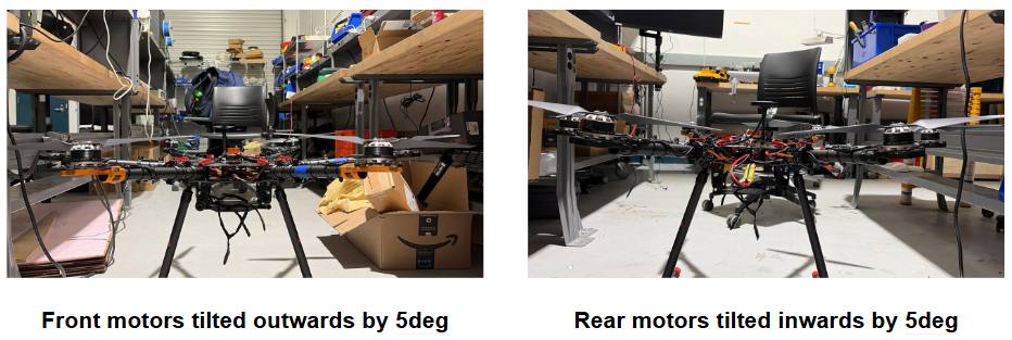
- Under-Actuated Flight– Yaw Response fixed: Front motors tilted outwards by 5deg. Rear motors tilted inwards by 5deg. Corrected the middle motors to 0deg tilt Installed larger, heavier propellers.
Date: 27 February 2026
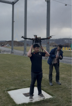
- Pre-flight Preparation: Installed the Cube Orange flight controller along with its associated peripherals, including the buzzer, USB port, and Herelink GPS module.
- System verification: Recalibrated all sensors. Practiced arming and emergency motor stops using the RC controller. Conducted a thrust and attitude response test.
- Maiden Flight: Test hardware integrity and have a stable testing platform for other subsystem tests. Result: Satisfactory. Observations: GPS ground course errors; Poor yaw control.
Date: 12 February 2026
- Integrated avionics, onboard compute, sensing, propulsion, and power systems onto the UAV airframe
- Performed electrical validation, power distribution checks, and signal integrity verification
- Conducted bench testing of motors, ESCs, sensors, and onboard compute
- Prepared the underactuated platform for initial flight testing

1.2 Localization Subsystem
Objective: Provide GPS-denied localization using onboard sensing and embedded compute using VIO and Optical Flow Subsystem.
Date: 2 April 2026
In the VIO subsystem the depth camera was tilted downwards by 30 degrees to capture features from ground this improved position accuracy when flying close to wall/surfaces. The performance was validated by performing near structure flights.

Date: 18 March 2026
VIO Subsystem: Integrated with the UAV and Flight test performed
Flight Test: Realsense Depth Camera is mounted facing the front of the drone. Stable Flight Mode- The system runs accurately, and the latency is low and acceptable. Localization error in XY is typically within 10–20 cm, with a maximum of 0.5 m
Optical Flow Subsystem: Benchmarking done with GPS module for Performance verification
Objective: To evaluate robustness of EKF2-based localization and dependence on GPS vs. optical flow across degraded environments.
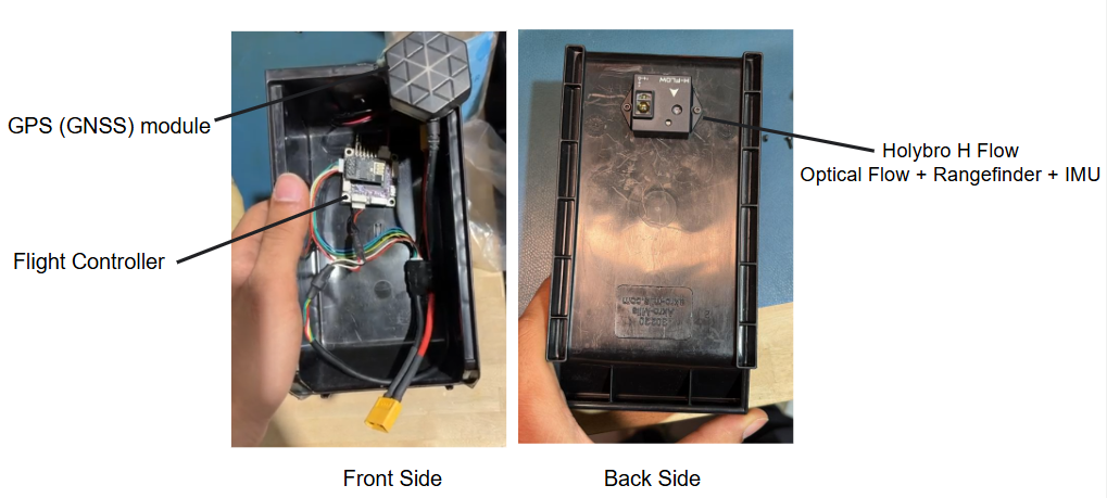
Multiple tests were conducted by moving the optical flow subsystem around NSH 1st floor, including close proximity to structures. The objective was to analyze flight logs to identify instances where EKF2 flagged the global position as invalid (indicating unreliable GPS, especially near structures). During these periods, the estimator relied solely on optical flow for velocity and altitude estimation. This behavior was validated by examining velocity plots at corresponding timestamps, which remained smooth—confirming proper EKF2 sensor fusion during GPS-denied conditions.

Date: 27 February 2026
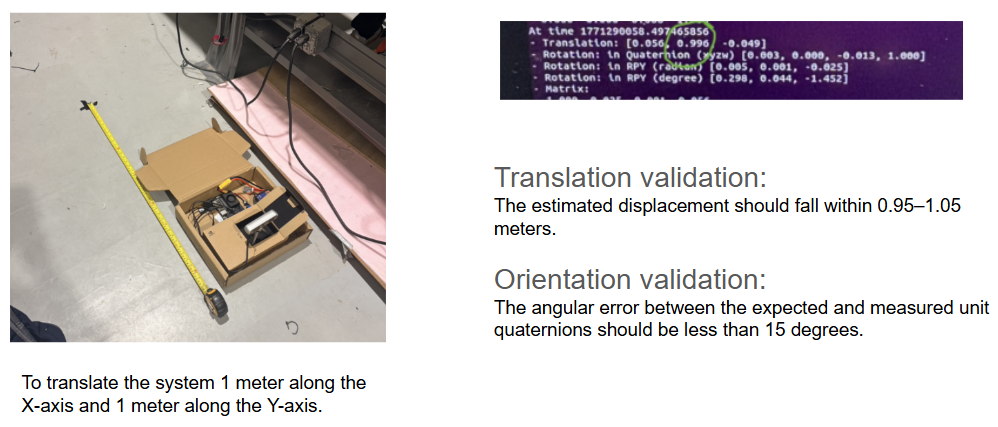
VIO/VSLAM Integrity Verification:
Date: 12 February 2026
VSLAM Setup and Verification:
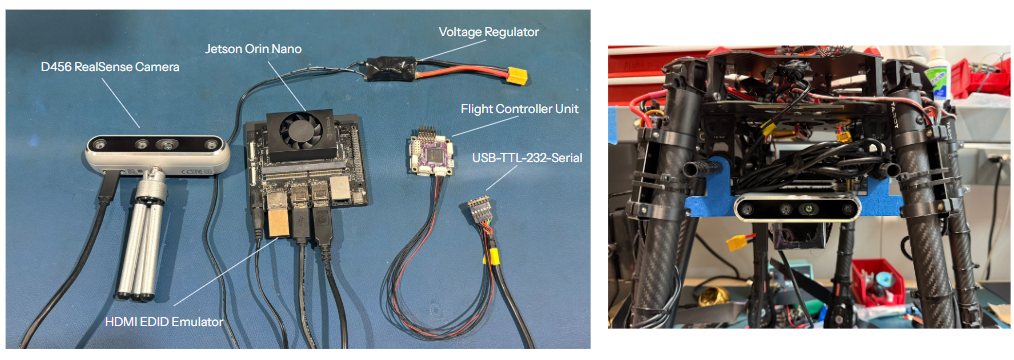
We set up and validated a Visual Simultaneous Localization and Mapping (VSLAM) pipeline on the NVIDIA Jetson Orin Nano using Isaac ROS Visual SLAM and the Intel RealSense D456. This work included flashing the platform with JetPack 6.0, installing and configuring the Isaac ROS VSLAM stack, and integrating the Intel RealSense SDK 2.0. We verified sensor data publication using the ROS 2 RealSense wrapper and containerized the VIO–RViz launch workflow into a Dockerfile, enabling reproducible and version-controlled execution of the VSLAM pipeline.
Current Status: VSLAM pipeline operational on the Jetson platform; validation ongoing under flight-representative conditions.
2. Simulation Subsystem (Algorithm Development & Validation)
This subsystem supports development, validation, and verification of algorithms prior to physical deployment.
2.1 PX4 Flight Control Stack Migration and Validation
Date: 12 February 2026
As part of the simulation subsystem, the team evaluated the custom modifications introduced by AirLab in PX4 v1.10 and selected PX4 v1.16 as the baseline for the Flying Hand project to ensure long-term support and compatibility. The PX4 stack was compiled and validated in Gazebo using the built-in omnidirectional vehicle model, achieving reliable takeoff and landing through QGroundControl. Building on this baseline, AirLab’s v1.10 modifications were systematically ported to PX4 v1.16, resulting in successful QGroundControl-based takeoff and landing of AirLab’s fully actuated aerial platform within the simulation environment.
2.2 Position–Wrench Hybrid Controller and Force Apply
Our controller is designed for a wall-interaction task in which a UAV takes off, approaches a wall, establishes contact, and then applies a constant normal force in a stable and compliant manner. The key challenge is to bridge two very different operating conditions: stable free-space flight before contact, and force-regulated interaction after contact. To address this, we developed a position–wrench hybrid controller that uses position control during takeoff, hovering, and wall approach, then transfers the wall-normal direction to a wrench controller once stable contact is detected. This allows the UAV to preserve flight stability while also regulating contact force in a controlled and repeatable way.
The key idea is not simply to combine two controllers, but to assign control authority according to both task phase and axis direction. Before contact, the UAV is governed by position tracking. After contact, the controller regulates force only along the wall-normal direction, while still holding the remaining directions in position. This design solves the main limitation of pure position control, which tends to keep pushing into the wall, and pure force control, which struggles to suppress lateral drift and altitude variation during contact.
2.2.1 Sub-System Architecture
The overall system follows a task-layer plus low-level control-layer architecture. The upper layer manages the state machine and mission logic, including takeoff, hover, approach, contact confirmation, steady-force holding, and retreat. The lower layer converts position targets or force targets into executable attitude-thrust commands for PX4 in offboard mode. In the implemented test pipeline, the script continuously publishes tracking_point during motion, and publishes ft_setpoint together with the wrench-mode switch during the contact-holding phase. This keeps the task logic modular and separates phase management from low-level control generation.
At the control-output level, the system uses a unified external attitude-thrust control chain throughout the entire mission, rather than sending velocity commands during free flight and switching to thrust commands only near contact. This avoids command discontinuities and thrust spikes during mode transitions. The implementation also aligns the relevant transforms so that the wall-normal control direction is explicitly associated with the x-axis, while the y and z axes remain available for position holding, and the command transmission frequency is matched to PX4 at 100 Hz.
Instead of averaging controller outputs with fixed weights, the system uses axis-wise fusion. The position controller produces the nominal thrust needed for free-space stabilization, while the wrench controller produces the normal-force correction in contact mode. The fused command assigns the x component primarily to wrench control and keeps the y/z components from position control, after which the final thrust vector is reconstructed into a feasible attitude-thrust command for PX4. This preserves physical consistency and avoids conflicts between control loops.

Hybrid Controller Architecture: This diagram reflects the task-layer/state-machine structure, the separate position and wrench control channels, the contact detection logic, and the final axis-wise fusion before commands are sent to PX4.
2.2.2 Execution Process

Task execution flow of the hybrid controller: The UAV completes takeoff, hover, and wall approach under position control, switches to hybrid control after stable contact is detected, maintains the target normal force, and then safely disengages and retreats.
Free-space flight
During takeoff, hover, and wall approach, the UAV is controlled entirely by the position controller. Using odometry together with position and velocity errors relative to the tracking_point, the controller computes a PID-based thrust command with hover-thrust compensation and reconstructs it into an executable attitude command. This supports takeoff, altitude stabilization, hover, and controlled approach to the wall. To improve approach safety, the logic also includes takeoff-stability criteria, hover settling time, and staged approach behavior. As the UAV gets close to the wall and weak contact tendencies begin to appear, the forward approach speed is reduced to lower impact at first contact.
Contact establishment
The critical issue is not merely detecting force, but recognizing when stable contact has truly been established. Switching to force control as soon as any force signal appears can cause a transient collision impulse to be misinterpreted as stable contact; keeping position control active for too long can produce overshoot, oscillation, or continuous inward pushing. To solve this, the controller uses a multi-condition contact-confirmation strategy based on a force window, duration condition, and altitude constraint. In one implementation, force control is enabled only when the measured force remains within 1.8–8 N for at least 0.15 s, around a target requirement of 5 N ±1 N. This makes the transition from approach to contact much smoother and more reliable.
Contact maintenance
Once contact is confirmed, the system enters a hybrid mode with force control along the x-axis and position holding along the y/z axes. The x-axis corresponds to the wall-normal direction, so the wrench controller closes the force loop there using the measured normal force and a target force reference. To improve stability, the force-feedback path includes two-stage filtering: median filtering suppresses spikes and outliers at contact onset, and moving-average filtering smooths the signal further. The controller also includes a normal-direction feedforward term to build the target force more quickly, and an x_hold damping term that adds a lightweight x-direction PD correction around the contact reference point. This prevents the UAV from gradually pressing deeper into the wall because of integral buildup, small attitude bias, or contact elasticity. Meanwhile, the y and z directions remain under position control to suppress lateral drift and altitude fluctuation during contact. After the task is completed, the wrench mode is disabled, the UAV returns to pure position control, retreats from the wall, and then descends.
2.2.3 Current Validation Results (3 April 2026)
Based on the two reports, the position–wrench hybrid controller has already been validated in simulation over the full sequence of takeoff, approach, contact establishment, steady-force holding, disengagement, and retreat. The current verified target is a steady wall-normal force of 5 N, with an error margin of ±1 N, maintained for 10 seconds. The reports also describe supporting visualization of force, thrust, position, and attitude to verify controller behavior and diagnose transform or transition issues.
At the same time, visual servoing has already been introduced to improve autonomous alignment and slow wall approach. The UAV can now approach the wall under VS-assisted fusion control, but the complete end-to-end pipeline from vision-guided approach to stable post-contact force regulation is not yet fully reliable. At the current stage, the hybrid position–wrench controller itself is the more mature and better-validated part of the system, while the vision-fusion extension remains under tuning and further testing.