The planning subsystem is critical to the navigation of the Pit Navigator project. This subsystem is responsible for generating the motor commands and navigating around the environment in a manner that will not cause the robot harm. This system takes in a known global map and a local map of its immediate environment and navigates through the local maps, avoiding known obstacles in the local map. The planning subsystem does this by generating motor commands, known as twist messages, that will safely move the rover to its goal location.
The algorithm that does this known as the TEB local planner. This algorithm was chosen over the base ROS planner because it produces optimal plans, which reduces energy use and increases speed made good by only traversing the shortest possible path. While it can take longer to plan an optimal path, we have found that the trade-off of time spent navigating and time spent planning favors an optimal path in our case when there are few obstacles to avoid.
In our current state, the global map also serves as our local map. The local map is a sliding window of the global map. Normally this local map is added to with /obstacles that represent untraversable terrain, but there are no publishers to that topic at this time. That means that this local map stays empty where the global map is empty and the robot will ignore obstacles that it encounters in the environment due to not perceiving and logging them.
These twist messages that the planner outputs are accepted by our simulated robot controller and will move the robot in simulation. The motor controller on Blue2 also accepts twist messages. This generalization to twist messages was made specifically to keep the code mostly rover independent, as it is the ROS standard, and will work on any ROS rover, as long as the rover has a configuration file that is known to the local planner.
The planner was demonstrated in Progress Review 10 and 11 on the rover. The specific validation criteria for the test that pertained to the ability of the navigation software was navigating to each waypoint to within 0.45 meters or a robot length away around a short track. The planner and localization code passed this criterion and also currently satisfies the performance requirement of planning an optimal path between waypoints in less than 20 seconds.
-

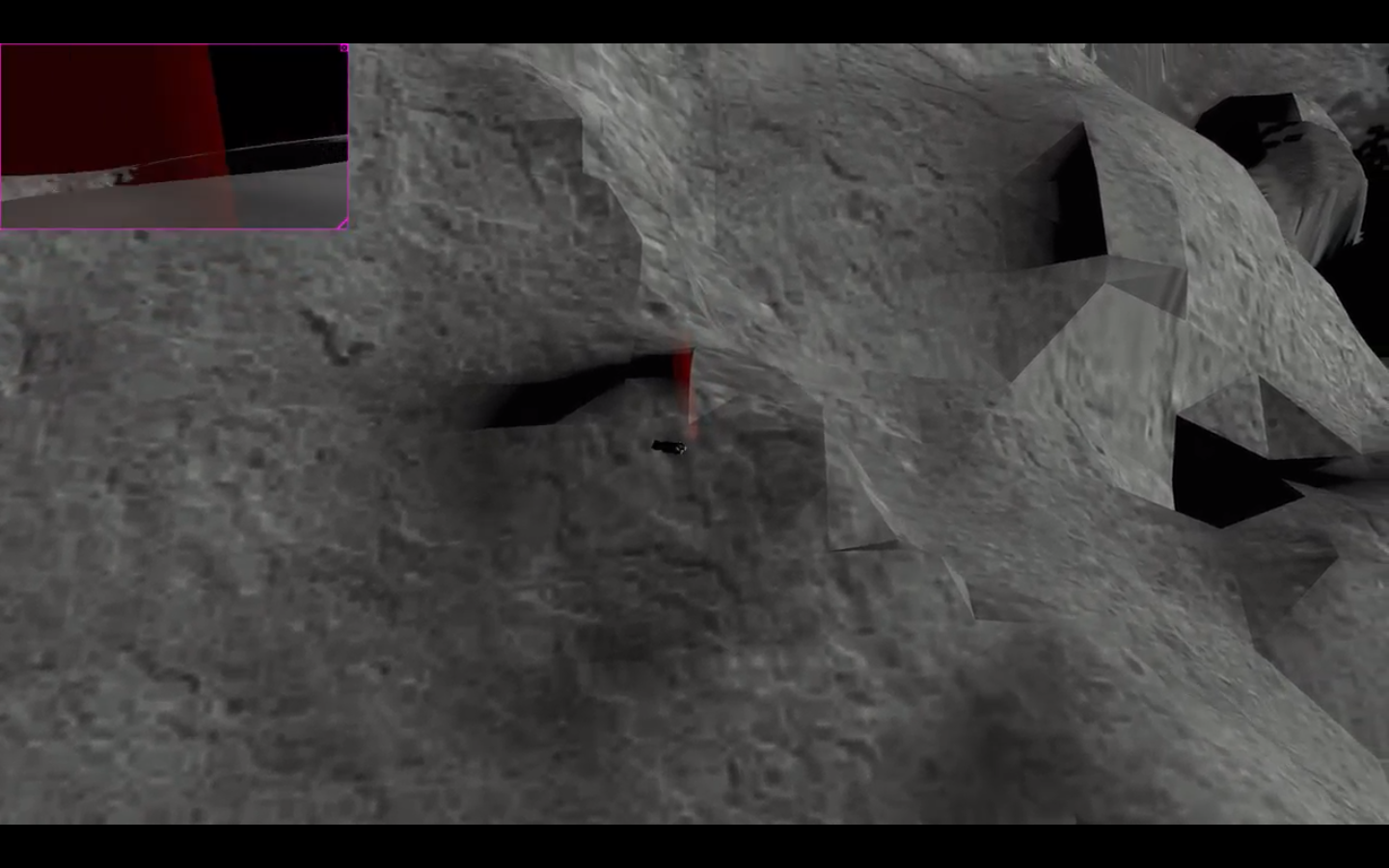
- Rover In Sim

-

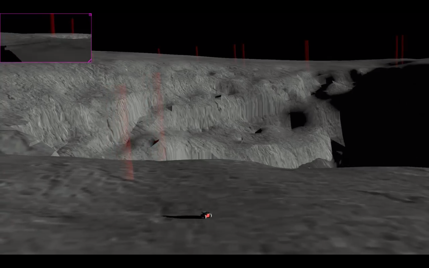
- Waypoint Traversal
-
- Waypoint Traversal
RISK ASSESSMENT
To begin accomplishing this risk assessment task, we needed to first determine the risk that we were assessing and managing. We decided to focus on two mission ending risks, running out of time due to lunar night, and falling into the pit. If the rover takes too long to complete its mission, then there will be incomplete results of the pit. If the rover tries to go too fast it might peer in the pit too many times before returning to the lander. The rover could fall in on the first trip to the pit and there might not be any results of the pit to show. The desirable solution is to return to the lander as much as possible without staying out too late.
To figure out what the right number of trips to the lander is, one will need to break down what the rover is doing into 3 categories of actions. The rover needs to travel between the pit and the lander (Pit-Lander action), the rover needs to advance to the next vantage point and take its pictures (Next-Vantage action), and the rover needs to travel around the pit at a safe distance to get to the vantage points from the pit area entrance (Pit-Vantage action). The Pit-Lander action is traveling along a long distance without interruption in two directions. We’ve assumed that the time it takes to complete this action is constant. If the vantage points are patterned every number of degrees, then the Next-Vantage action can also be assumed constant as the distance traveled and actions entering the pit will all take the same amount of time. Finally, the Pit-Vantage action is harder. The Pit-Vantage action counts the time it takes to reach any point around the pit from one point on the circumference of the pit. Assuming that the pit resembles a circle from above, the rover has to travel a distance of pi*r to reach the furthest possible vantage point on the pit to safely travel around the pit. The rover could also travel 0 distance to reach the closest possible vantage point. This leads me to believe that the Pit-Vantage action time should be averaged to be the time to travel pi*r/2 distance. Once an estimate for the time it takes to accomplish each of these actions is accomplished one can use the following formula to solve to find the right number of trips to the lander.
Formula 1:
Trips = (Time_Available-Next_Vantage*Unvisited_Vantage)/(Lander_Pit*2+Pit_Vantage*2)
In Formula 1, Time_Available is the time allotted to complete the mission, and Unvisited_Vantage is the number of vantage points that the rover still needs to take pictures of the pit from. Any partial trips need to be rounded down so that the number of trips is a whole number. Next_Vantage, Lander_Pit, and Pit_Vantage are the time estimates of how long each action takes. As the rover starts doing these actions it can update these estimates with historical data, to get more accurate predictions. During the update step, we recommend using a weighted average to trust the historical data greater than the estimate.
FINAL STATUS OF THE PLANNING SUBSYSTEM
The path planning and risk management subsystem is made of 3 parts. The global planner, the local planner, and the state machine. The global planner is responsible for using the obstacle map made from orbital imagery to find a path to the next waypoint. The local planner is responsible for sending the hardware commands to make the robot follow the path set by the global planner. The state machine is responsible for determining which waypoint the global planner plans to next. Combined, these parts tell the robot how to move its wheels to get to where it needs to go.
This subsystem runs in the onboard rover computer, the Intel Nuc. The three different parts use the ROS package, move base, to communicate with each other. Each part uses a different ROS package to operate. The local planner uses the TEB local planner package, the global planner uses the ROS global planner package, and the state machine uses the executive smach package. The state machine will send a new destination to move base, which will pass the message along to the global planner. The global planner will plan the optimal path between the start and goal positions of the rover. Move base takes this path and hands it over to the local planner which will follow the path by taking the robot’s position, also gathered by move base, and outputting motor commands. When the local planner has decided that the robot has reached the goal position, it flags move base, which flags the state machine to send a new goal position.
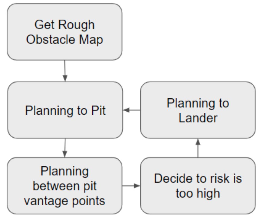
State Machine Flow Diagram 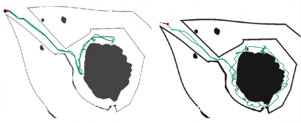
Rover Paths During The Mission (Left: First Trip, Right: Complete Mission)