
System Requirements
- The UAV should detect fiducial markers at a height of 5m (detection rate > 80%).
- The UAV should localize the fiducial markers with respect to one another accurate (error between fiducial locations < 30 cm).
- The UAV should fly to a target GPS location (within a 5m radius).
- The AGV should avoid ground obstacles (success rate > 80%).
- In a 50x50m field, the AGV should reach the target location quickly ( < 15 min).
- In a 50x50m field, the AGV should reach the target location accurately ( < 3 m radius).
- In a 50x50m field, the AGV should reach the target location successfully ( >80%).
Functional Architecture
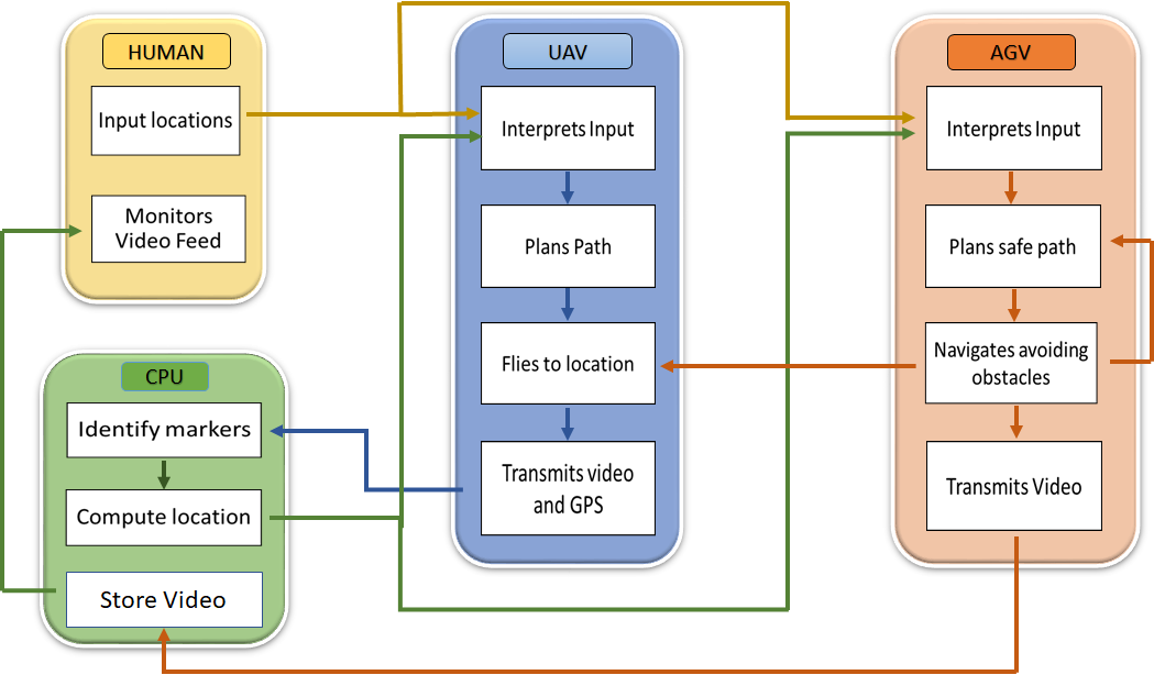
Our functional architecture can be divided into three major functions: the UAV perceives the environment, the CPU identifies the obstacles and plans the path for the AGV and the UAV, and the AGV navigates to the target destination. Each function can be further explored in more detail. The UAV needs to simultaneously capture a birds-eye video view for the CPU while also exploring the environment for the next fiducial marker. The CPU acts as the bridge between the AGV and the UAV. Using the video feed from the UAV, it generates an internal map of the different fiducial nodes, determines which nodes comprise a traversable path, and forward this information to the AGV. It simultaneously provides the map back to the UAV so that the UAV can explore the most optimal areas. The AGV takes in the higher level commands from the CPU and travels to the target location. It uses its own onboard sensors to perform obstacle avoidance on static objects.
Cyberphysical Architecture
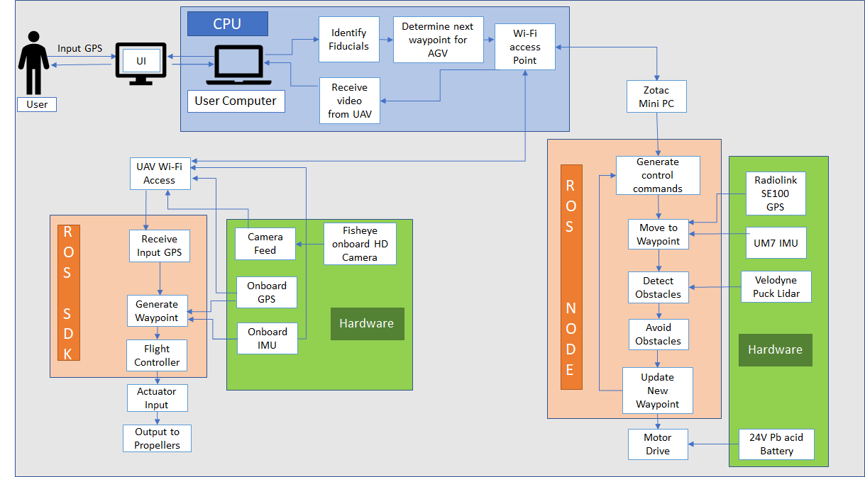
Our cyberphysical architecture shines some more light into the exact implementation of our system. At the highest level, we have 3 different nodes that represent the individual agents in our system. The UAV (Bebop 2 Drone) is represented by the ROS SDK, the CPU is the central command center of our system, and the AGV (Clearpath Husky) is represented by the ROS Node. The entire system is distributed over a ROS WiFi network where the AGV, the UAV, and the CPU are all on different computers. It is important to note that for both the AGV and the UAV, we do not have direct control and instead we interact via a ROS API. Similar to the functional architecture, the CPU acts as the main computational unit of our system. It generates an internal map with the video feed from the Bebop 2, localizes the UAV, the AGV, and the traversable paths, and provides the target locations to both the UAV and the AGV. The ROS SDK node converts the target location into roll/pitch/yaw commands and feeds the video to the CPU. The ROS node’s main responsibility is lower-level path planning: specifically obstacle avoidance.
Subsystems
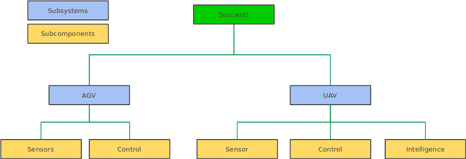
We have divided our entire system into 5 major subcomponents. For the AGV, we have sensing with the GPS and the Velodyne Puck and control for obstacle avoidance and navigation. For the UAV, we have sensing with the Bebop 2 Camera and GPS, control for GPS waypoint navigation, and intelligence for sensor fusion and an exploration algorithm to find the next fiducial marker.
AGV Sensors: The AGV is equipped with enough sensors such that it can navigate with or without AGV assistance (this is for comparative purposes). As a result, it combines GPS (SE100) data and IMU with point clouds from the Velodyne Puck to localize and avoid obstacles. The main considerations in the design of this subsystem are the types of sensors to be used. GPS was required because the CPU sends GPS coordinates as the target location. The Velodyne Puck was originally not part of our design choice as it comes with a non-trivial price tag and thus we were originally considering a stereo sensor such as the ZED camera. However, Captain Dolan has been able to procure two Pucks from Velodyne and has been gracious enough to lend us one.
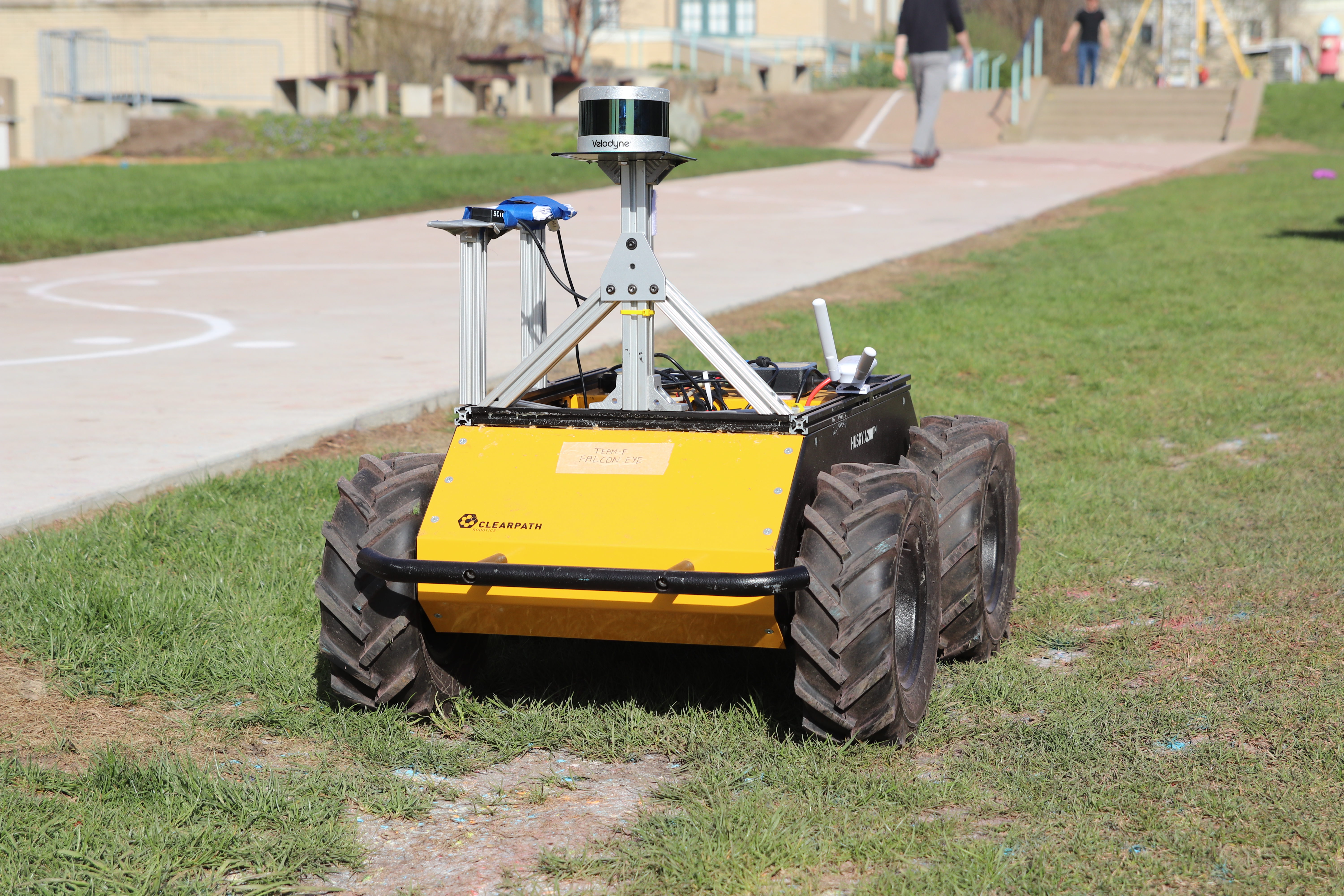
Sensors and mount for the Husky.
UAV Sensors: The UAV sensors provide the aerial data feed necessary to help the AGV localize itself and detect traversable paths that are beyond its field of view. The choice of UAV sensors is dictated by the choice of UAV; as we have decided to use the Bebop 2, we have access to a 720p fisheye lens with auto stabilization and a GPS module. The Bebop 2 was chosen for 3 main reasons. First, the Bebop 2 has excellent developer support and ROS integration. It has an SDK that is available and because the official app was built with the SDK, it can be said that the developers have full control over the drone. Second, the Bebop 2 is cheap (~300) and thus we justified it as a prototyping platform that we can replace if it breaks. Third, the drone had already been ordered by our advisor and thus it was the fastest way for us to gain access to a development platform. The video feed is first fed through a filter that removes noise, then it is picked up by the April Tags ROS node. The tf output is passed through a low-pass filter to stabilize the reading before it is published as individual locations with respect to the home frame. The GPS reading from the drone is also passed through a low-pass filter and it is combined with the base link frame to get the GPS coordinates of all the fiducial markers.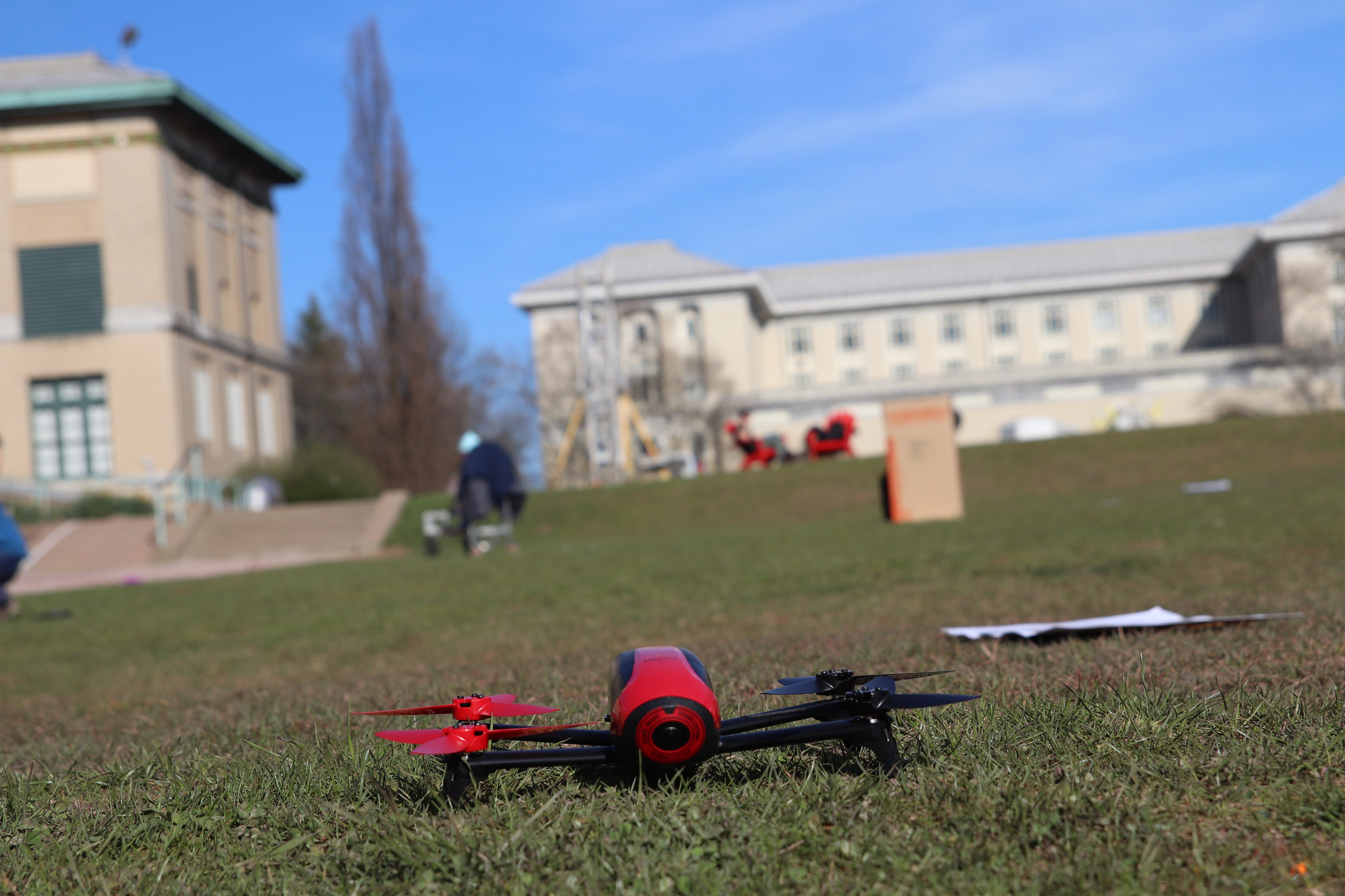
Sensors on UAV
AGV Control:
a) AGV Obstacle Detection
The AGV generates environment map using a LIDAR sensor. A LIDAR usually consists of a scanner and a laser. The laser emits a laser beam at a certain frequency and also receives the reflected laser beam from an object on the path of the laser. This can be used to estimate the distance between the LIDAR sensor and the object by estimating the time difference between the transmitted and received laser. This method is a very reliable method of estimating the distance up to a certain limit depending upon the LIDAR specifications. We have selected Velodyne VLP 16 sensor due to its excellent online support and reliability. As shown in the figure given below, first one depicts the raw point cloud which we get from the Velodyne, then using the PCL library, we filtered out the obstacles of our interest i.e, which are greater than a certain threshold height and which are in the proximity of the AGV, which is shown in the second figure.

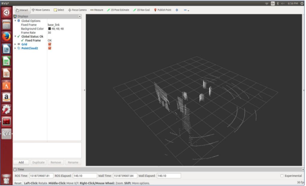
Velodyne raw and filtered outputs
b) Path Planning and Obstacle Avoidance
We used ROS navigation stack for optimized localized-navigation. It uses Search based planning algorithm like A* and has proven to be very effective for motion planning. We integrated GPS and IMU data with this stack for global localization and planning. In addition to this augmenting this system with the input from the Velodyne, helped us in developing a complete obstacle detection and avoidance system. We were able to demonstrate that our system is able to detect and avoid, static as well as dynamic obstacles.
For the global level of path planning our final system was able to record the GPS location given by the UAV on the waypoint navigation text file. The husky navigation stack was reading that file sequentially and executing the path goals provided by the UAV. Two figures given below show the husky navigation with and without obstacle avoidance.
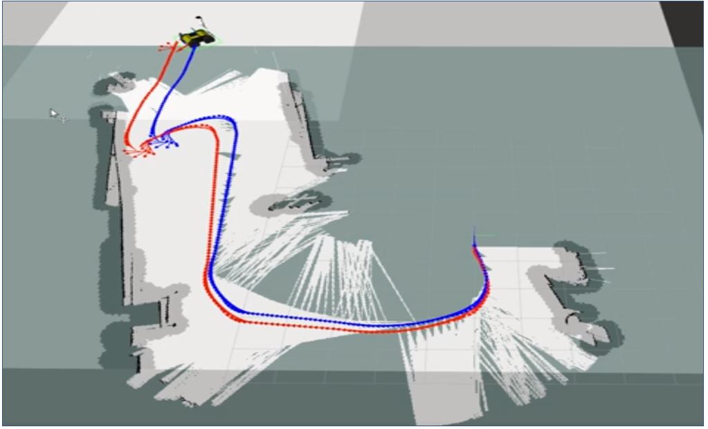
Husky Path Planning without Obsctacles
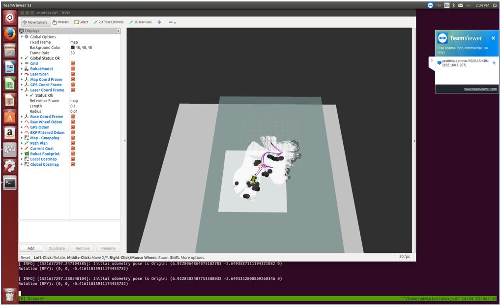
Husky Path Planning with Obstacle Avoidance
UAV Control:
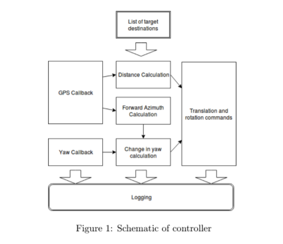
UAV control is the lower level controller for the Bebop 2 drone. This controller is in charge of navigating the Bebop 2 toward a GPS location. For this, we implemented our own custom controller that first orients the drone into the correct heading and moves forward. Although simple in theory, we also added an exponentially decaying scale factor for the throttle such that the movements would be smoother. Additionally, we added a dynamically adjustable height controller to ensure that the drone flew at 10m. Although the odometry may drift over time, we correct this drift via true readings from the April Tag detections. The orientation and translation commands are shown in a diagram below.
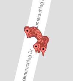
UAV Intelligence:
The UAV Intelligence subsystem the subsystem that is responsible for the exploration as well as the pathfinding for both the UAV and the AGV. The reason why it is considered to the UAV Intelligence is due to its implementation. Internally, we represent all the April Tags as vertices in a graph. These vertices are connected by an edge if the vertices are less than 3 meters apart. Vertices represent non-obstructed areas in the world and the edges represent valid paths between these areas. Both explorations for the UAV and global path planning for the AGV are built on top of this graph representation. Exploration for the UAV is an iterative process whereby the closest unexplored April Tag vertex and the surrounding area is visited (marked as explored). The AGV is bounded by the vertices of the graph and uses an A-star algorithm to traverse through the environment. A high-level diagram of this process is shown below.
