Mandatory Performance Requirement
- M.P.1 Will operate at speeds up to 5 m/s
- M.P.2 Will have a positional precision of 2m
- M.P.3 Will operate at maximum wind speeds of 5km/h
- M.P.4 Will achieve a detection accuracy of 70%
- M.P.5 Will achieve classification accuracy of 80%
- M.P.6 Will have a grasp success rate of 30%
- M.P.7 Will grasp blocks of 1.5kg
- M.P.8 will grasp blocks of 1.2 x 0.2 x 0.2m
- M.P.9 Will detect poor grasp with 70% success rate
- M.P.10 Will transport blocks with a 70% success rate
- M.P.11 Will place blocks with precision of 0.1m
- M.P.12 Will assemble wall of 3 layers
- M.P.13 Will detect poor placement with a 50% success rate.
Non Mandatory Performance Requirement
- M.N.1 Will have a manual overwrite safety feature
- M.N.2 Will be easy to operate
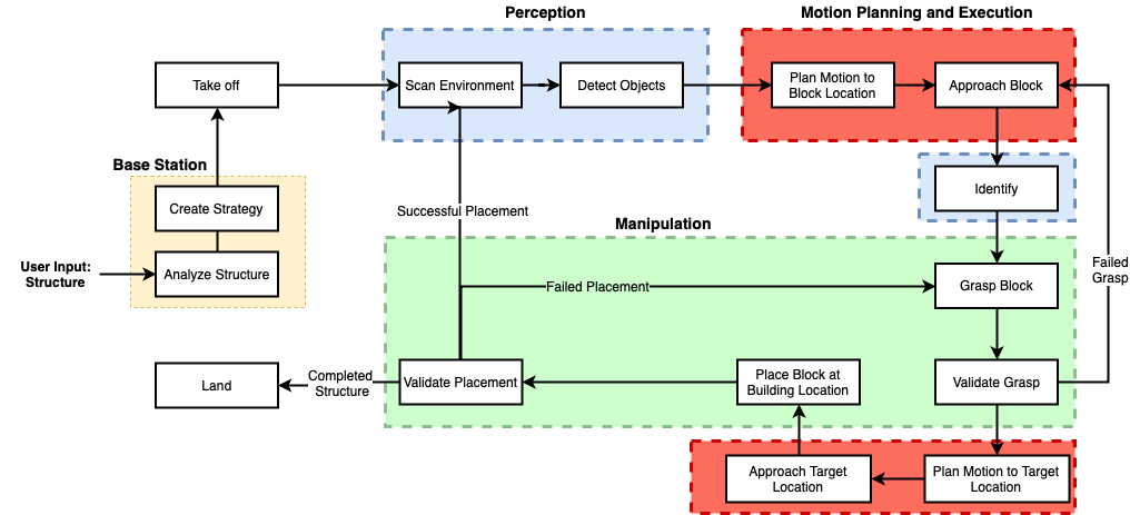
Functional Architecture:
Cyberphysical Architecture
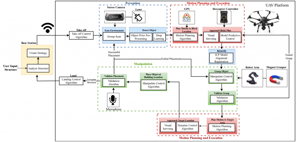
System Description:
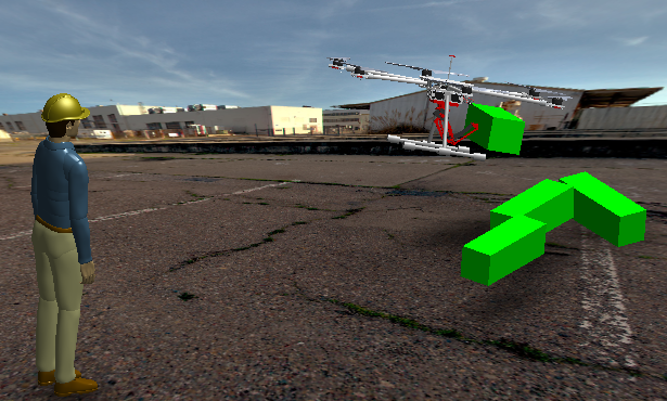
Our system uses a hexacopter platform with manipulator attached to pick up
blocks for construction purposes.
1. External Base Station
The external base-station consists of an workstation (preferably a laptop, because
it is portable), that is capable of sending commands or simple instructions to the
hexcopter platform, and receiving feedback messages. Here, we use the workstation
to analyze to further analyze a structure provided by the user. The workstation
will work on creating a pick-up routine or schedule based on best order picking and
placement.
2.Perception
2.1 Block Detection
We employ a set of algorithms that enable us to detect blocks from both a farther
range (as a part of scene understanding), as well as at close range. We use basic
object priors such as colors and depth regions to reduce the search space, and pass
these regions through a low computation object detection network pretrained to
detect blocks in simulation and create an initial set of bounding boxes around the
blocks. The goal is to reach within 2m accuracy of the point from where all the
blocks are visible so as to ensure reliable servoing.
2.2 Block Identification System
The block isolation system, or the pick-best-block algorithm is mainly used to pick
the best block given a candidate set of bounding boxes. Here, we will use the fusion
of visual information from different sources to pick:
- Depth Map estimation (using Stereo camera)
- Surface Normal estimation
- Grasp Point Visibility
- ICP based pose check
This information shall ensure we are able to pick the block that is easiest to servo to-
wards. It is important to note, that we reuse the Block Identification algorithm even
after we have reached the desired pose after servoing, to ensure that the alignment
error is low.
3.Motion Planning and Execution
Planning and Execution tasks using the hexcopter controller will be categorized
within this subsystem. We will be using the PixHawk 2 Cube flight controller to
execute low level control tasks. Further, we will rely on a GPS sensors for course
localization, and to comply with the rules of the challenge, rely on visual methods
for fine localization. Our planning and control tasks are exectued in three phases:
3.1 Waypoint Navigation
This set of nodes executes simple waypoint navigation to reach a waypoint. We
will be using the GPS sensor information with an Extended Kalman Filter of the
controller to plan and execute simple point-to-point navigation tasks. The EKF
functionality is already implemented in the controller.
3.2 Visual Servoing
Visual Servoing is an important component of our motion planning subsystem. We
will be using the visual information from the block identification system to servo
towards blocks to pickup and adjacent to blocks during placement. Our method uses
the visual information used for block identification. We apply small control inputs
in order to reduce the overall pose error between the current and desired block pose.
3.3 Dynamic Contoller
The Dynamic Controller is an adaptive control methodology to dynamically han-
dle the combined payload of the block and the manipulator arm at the time of
transporting the block for placement
4.Manipulation
The Manipulation Subsystem includes all the components responsible for the move-
ment and control of the manipulator arm and the end-effector to lift the blocks. We
will be using an electromagnetic end-effector since, as explained earlier, our blocks
will include metal patches on the surface. For the low level control of the arm we
will be using a ARM-32 microcontroller interfaced with ROS-Serial to allow direct
communication with the TX2. The manipulator control algorithms will be sim-
ple forward kinematics given some point with respect to the current frame of the
platform.
4.1 Grasp Validation
Grasp and Placement Validation are important aspects of our final system. We
will be using a contact microphone as a method of ensuring tactile contact with
the block. For the grasp validation, to ensure we can reliably lift the block we will
utilize a force sensor based method, so that we can apply a certain thrust (within a
threshold) and check the time to ensure the block has been lifted. We will be relying
on visual methods (such as plane continuity) to ensure the blocks has been placed
correctly with respect to other blocks in the placement zone.